1. Introduction
The EVTSCAN HWP-T804-01-23-HL-P is a smart direct-insertion liquid level light column controller designed for precise pressure and liquid level measurement. It features advanced digital filtering technology for strong anti-interference capabilities, ensuring stable and reliable readings even in challenging industrial environments. This controller is widely applicable in various settings requiring accurate liquid level monitoring and control.
Key Features:
- Advanced Digital Filtering: Utilizes digital filtering technology to effectively identify and suppress low-frequency disturbances and irregular interferences in the measurement signal, ensuring high stability.
- High Measurement Accuracy: Provides precise pressure value measurements with high accuracy, ensuring stable and credible results.
- Easy Installation: Designed for common installation sizes, making it easy to install, maintain, and replace with existing instruments.
- Efficient Heat Dissipation: Features a porous heat dissipation design to maintain good permeability and ensure stable operation with improved cooling.
- Wide Application Range: Suitable for water treatment plants, wastewater treatment plants, urban water supply, high-level pools, water wells, mines, industrial water systems, water tanks, oil pools, hydrogeology, reservoirs, rivers, and oceans.
2. Product Components
The package for the HWP-T804-01-23-HL-P Pressure Controller typically includes:
- 1 x HWP-T804-01-23-HL-P Light Column Controller Unit

Figure 2.1: Front and side view of the HWP-T804-01-23-HL-P Pressure Controller. This image shows the main display, control buttons, and the overall compact design of the unit.
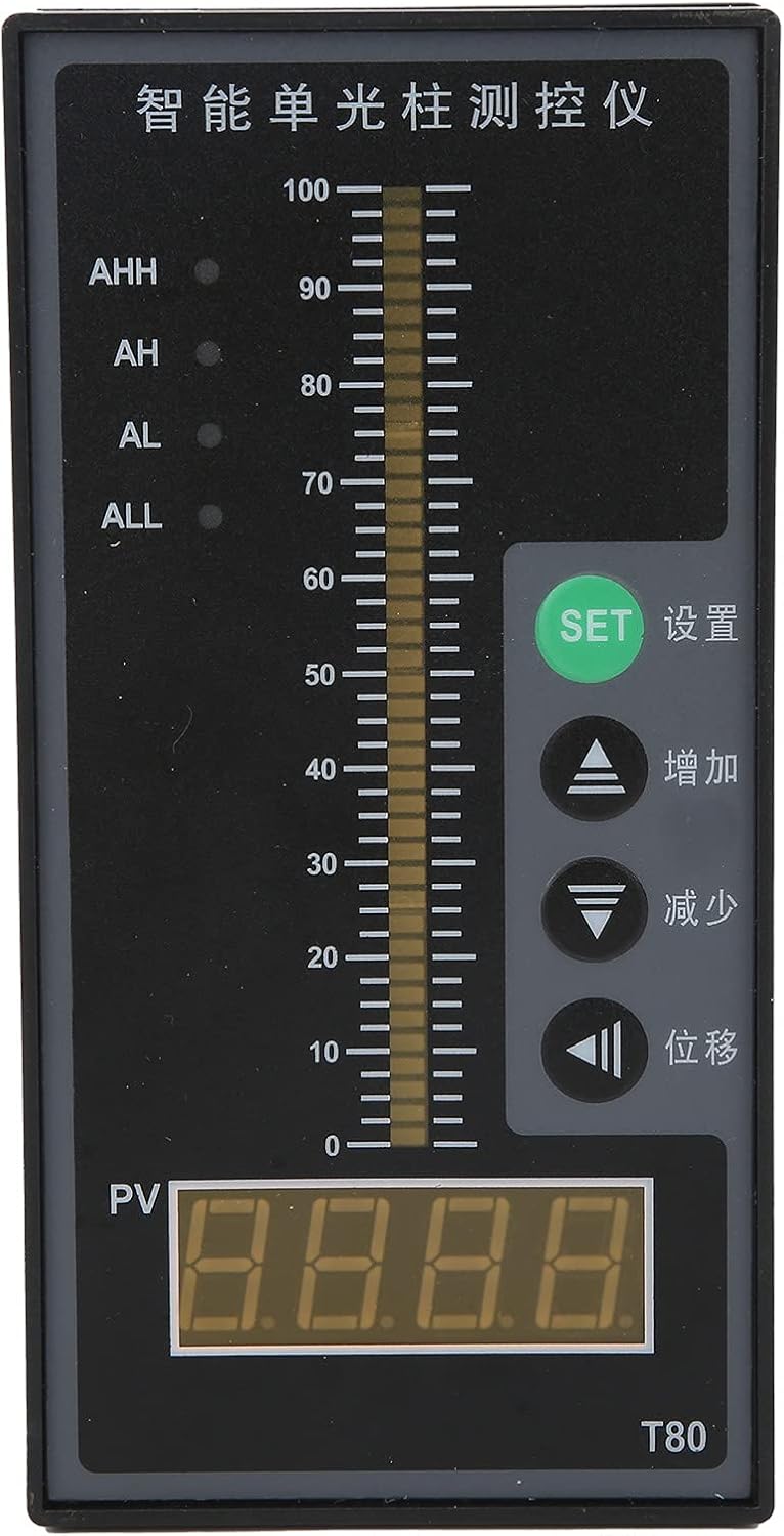
Figure 2.2: Detailed front view of the controller, highlighting the digital display (PV), the light column indicator, and the control buttons (SET, Increase, Decrease, Shift).
3. Specifications
| Parameter | Value |
|---|---|
| Model | HWP-T804-01-23-HL-P |
| Material | ABS |
| Power Supply Voltage | AC 220V 50HZ |
| Measurement Accuracy | 0.5% FS |
| Power Consumption | ≤5 W |
| Measurement Range | -1999 ~ 1999 words |
| Accuracy | ±0.5% FS±1 word or ±0.2%FS±1 word (light beam accuracy 1%) |
| Resolution | 0.001, 0.01, 0.1, 1 |
| Sampling Cycle | 3 times/second |
| Output | Four-way relay alarm control output |
| Thermal Resistance Signal Input | Pt100, Cu50 |
| Thermocouple Input | B, S, E, K, J, T, R, N |
| Standard Current Input | 0-10/0-20/4-20 mA |
| Standard Voltage Input | 0-5/1-5 V |
| Resistance Input | 0-400 Ω |
| Non-Standard Voltage Input | 0-100 mV |
| Frequency Input | 0-3 KHz, amplitude > 4 V (square wave or sine wave) |
| Standard Output Voltage | 0-5 V, 1-5 V (Load RL > 250 kΩ) |
| Standard Analog Current Output | 0-10 mA (Load RL < 750 Ω) |
| Power Output | 24 V DC |
| Load Capacity (Power Output) | ≤30 mA |
| Control Output Contact Capacity | 22 V AC/5 A (resistive load) |
| ASIN | B09Q8531QN |
| Manufacturer Reference | EVTSCAN9abzvco7yi |
4. Setup
Proper installation is crucial for the accurate and safe operation of the HWP-T804-01-23-HL-P Pressure Controller. This unit is designed for standard industrial panel mounting.
4.1 Mounting
- Panel Cutout: Ensure the panel cutout dimensions match the controller's specifications for a secure fit.
- Insertion: Carefully insert the controller into the panel cutout from the front.
- Securing: Use the provided mounting brackets or clips to secure the controller firmly in place from the rear of the panel.
- Ventilation: Ensure adequate space around the controller for proper air circulation, especially around the porous heat dissipation areas on the sides, to prevent overheating.

Figure 4.1: Side view of the controller, showing the porous heat dissipation design. Ensure these areas are not obstructed during installation.
4.2 Electrical Connections
All electrical connections should be performed by qualified personnel in accordance with local electrical codes and regulations. Ensure power is disconnected before making any connections.
- Power Supply: Connect the AC 220V 50HZ power supply to the designated power terminals on the controller. Refer to the wiring diagram on the unit or in the detailed product documentation for correct polarity and terminal assignments.
- Signal Input: Connect your pressure or liquid level sensor to the appropriate signal input terminals. The controller supports various inputs including 0-10/0-20/4-20 mA current, 0-5/1-5 V voltage, Pt100/Cu50 thermal resistance, and various thermocouple types (B, S, E, K, J, T, R, N). Ensure the sensor type matches the controller's configuration.
- Control Output: Connect external alarm devices or control systems to the four-way relay alarm control output terminals as required by your application. The contact capacity is 22 V AC/5 A (resistive load).
- Analog Output (Optional): If using the standard analog current (0-10 mA) or voltage (0-5 V, 1-5 V) outputs, connect them to your receiving devices.
- Power Output (Optional): The 24 V DC power output can be used to power compatible external sensors or devices (load capacity ≤30 mA).
Note: Always verify wiring against the specific terminal block diagram provided with your unit to prevent damage.
5. Operating Instructions
The HWP-T804-01-23-HL-P controller features a clear digital display (PV) and a light column indicator for real-time measurement visualization, along with intuitive control buttons for configuration.
5.1 Display Overview
- PV (Process Value) Display: The large digital display shows the current measured pressure or liquid level value.
- Light Column Indicator: Provides a visual representation of the measured value relative to the full scale, with markings from 0 to 100.
- Alarm Indicators (AHH, AH, AL, ALL): LEDs indicate the status of the four alarm levels (High-High, High, Low, Low-Low).

Figure 5.1: Front view of the controller, showing the PV display, light column, and alarm indicators.
5.2 Control Buttons
- SET (设置): Used to enter parameter setting mode and confirm selections.
- Increase (增加): Used to increment values or navigate through menu options.
- Decrease (减少): Used to decrement values or navigate through menu options.
- Shift (位移): Used to shift the cursor during parameter entry or to access specific functions.
5.3 Basic Operation
- Power On: After ensuring all connections are secure, apply AC 220V 50HZ power. The controller will power on and display the current measured value (PV).
- Monitoring: Observe the PV display and the light column indicator for real-time pressure or liquid level readings. The alarm LEDs will illuminate if the measured value exceeds or falls below the set alarm thresholds.
- Setting Parameters:
- Press the SET button to enter the parameter setting mode.
- Use the Increase and Decrease buttons to navigate through different parameters (e.g., alarm setpoints, input type, resolution).
- Press SET again to select a parameter for editing.
- Use Increase, Decrease, and Shift buttons to adjust the value.
- Press SET to confirm the new value and move to the next parameter or exit the setting mode.
- Alarm Configuration: Configure the AHH, AH, AL, and ALL alarm setpoints according to your application requirements. When the measured value crosses these thresholds, the corresponding relay output will activate.
Refer to the detailed programming guide (if available with your specific unit) for advanced parameter settings and calibration procedures.
6. Maintenance
Regular maintenance ensures the longevity and optimal performance of your HWP-T804-01-23-HL-P Pressure Controller.
- Cleaning: Periodically clean the front panel and display with a soft, dry cloth. Avoid using abrasive cleaners or solvents that could damage the surface.
- Ventilation: Ensure that the porous heat dissipation vents on the sides of the unit remain clear of dust and debris. Blocked vents can lead to overheating and affect performance.
- Connection Check: Regularly inspect all electrical connections for tightness and signs of corrosion. Loose connections can lead to intermittent operation or inaccurate readings.
- Environmental Conditions: Ensure the operating environment remains within the specified temperature and humidity ranges to prevent damage to internal components.
- Calibration: While the unit is designed for high accuracy, periodic calibration by a qualified technician may be necessary depending on the application and regulatory requirements.
7. Troubleshooting
This section provides solutions to common issues you might encounter with the HWP-T804-01-23-HL-P Pressure Controller.
| Problem | Possible Cause | Solution |
|---|---|---|
| No display/Unit not powering on | No power supply; Incorrect wiring; Blown fuse (internal/external) | Check AC 220V 50HZ power connection. Verify wiring according to the diagram. Check for tripped circuit breakers or blown fuses. |
| Inaccurate or fluctuating readings | Sensor issue; Loose signal connections; Electrical interference; Incorrect input type setting | Verify sensor operation and calibration. Tighten signal wiring. Ensure proper grounding. Check if the input type setting in the controller matches your sensor. |
| Alarm not triggering/Incorrect alarm behavior | Incorrect alarm setpoints; Relay wiring issue; Alarm logic misconfiguration | Review and adjust alarm setpoints (AHH, AH, AL, ALL). Check wiring to external alarm devices. Verify alarm logic settings in the controller. |
| Controller feels hot | Blocked ventilation; Overload on power output | Ensure heat dissipation vents are clear. Reduce load on the 24V DC power output if applicable. |
| Buttons unresponsive | Temporary software glitch; Physical damage | Try power cycling the unit. If the issue persists, contact technical support. |
If the problem persists after attempting these solutions, please contact EVTSCAN technical support for further assistance.
8. Warranty and Support
For warranty information, please refer to the terms and conditions provided at the time of purchase or contact your vendor. EVTSCAN is committed to providing reliable products and support.
Spare Parts Availability:
Information regarding the availability of spare parts for the HWP-T804-01-23-HL-P Pressure Controller is currently unavailable. Please contact your supplier or EVTSCAN customer service for inquiries.
Contact Information:
For technical support or service inquiries, please visit the official EVTSCAN store on Amazon or contact their customer service channels. You can find the EVTSCAN store at: EVTSCAN Amazon Store


