1. Introduction
This manual provides detailed instructions for the DORHEA Buck Boost Converter Adjustable Voltage Regulator (Model: 3cf9aadc-ccbd-42cc-ba3e-50aa13bec481). This device is designed to convert an input DC voltage (6V-36V) to a stable, adjustable output DC voltage (0.6V-36V) with constant current capabilities. It features a digital display for monitoring various parameters and includes multiple protection functions for safe operation.
2. Safety Information
- Ensure correct input and output polarity before connecting the device. Reverse polarity can cause damage.
- Do not exceed the maximum input voltage (36V) or output current (5A) specifications to prevent damage or malfunction.
- Operate the converter in a well-ventilated area to prevent overheating.
- Avoid contact with live terminals during operation.
- This device is intended for use by individuals familiar with basic electronics and electrical safety procedures.
- In case of smoke, unusual odors, or abnormal operation, immediately disconnect power.
3. Product Overview
The DORHEA Buck Boost Converter is a versatile power supply module featuring a clear digital display and intuitive controls. It can step up or step down voltage, maintain constant current, and offers various protection mechanisms.
3.1 Key Features
- Wide Input/Output Range: Input DC 6V-36V, Output DC 0.6V-36V.
- Adjustable Parameters: Output voltage adjustable in 0.01V increments, output current adjustable in 0.001A increments.
- Multi-function Display: Shows input/output voltage, current, temperature, power, electric capacity (AH), electric quantity (WH), and running time. Includes voltage and current graph interface.
- Customizable Display: Ability to flip/rotate display, change background/parameter colors, and switch day/night modes.
- Comprehensive Protection: Includes over-voltage protection (OVP), over-current protection (OCP), over-power protection (OPP), low-voltage protection (LVP), over-temperature protection (OTP), reverse protection, and short circuit protection.
- Power-off Memory: Retains settings after power loss.
3.2 Component Identification

Figure 1: Front View of the Converter. This image shows the front panel of the DORHEA Buck Boost Converter, featuring the digital display, the rotary encoder knob for adjustments, and the ON/OFF button. Input and output terminals are visible at the bottom.
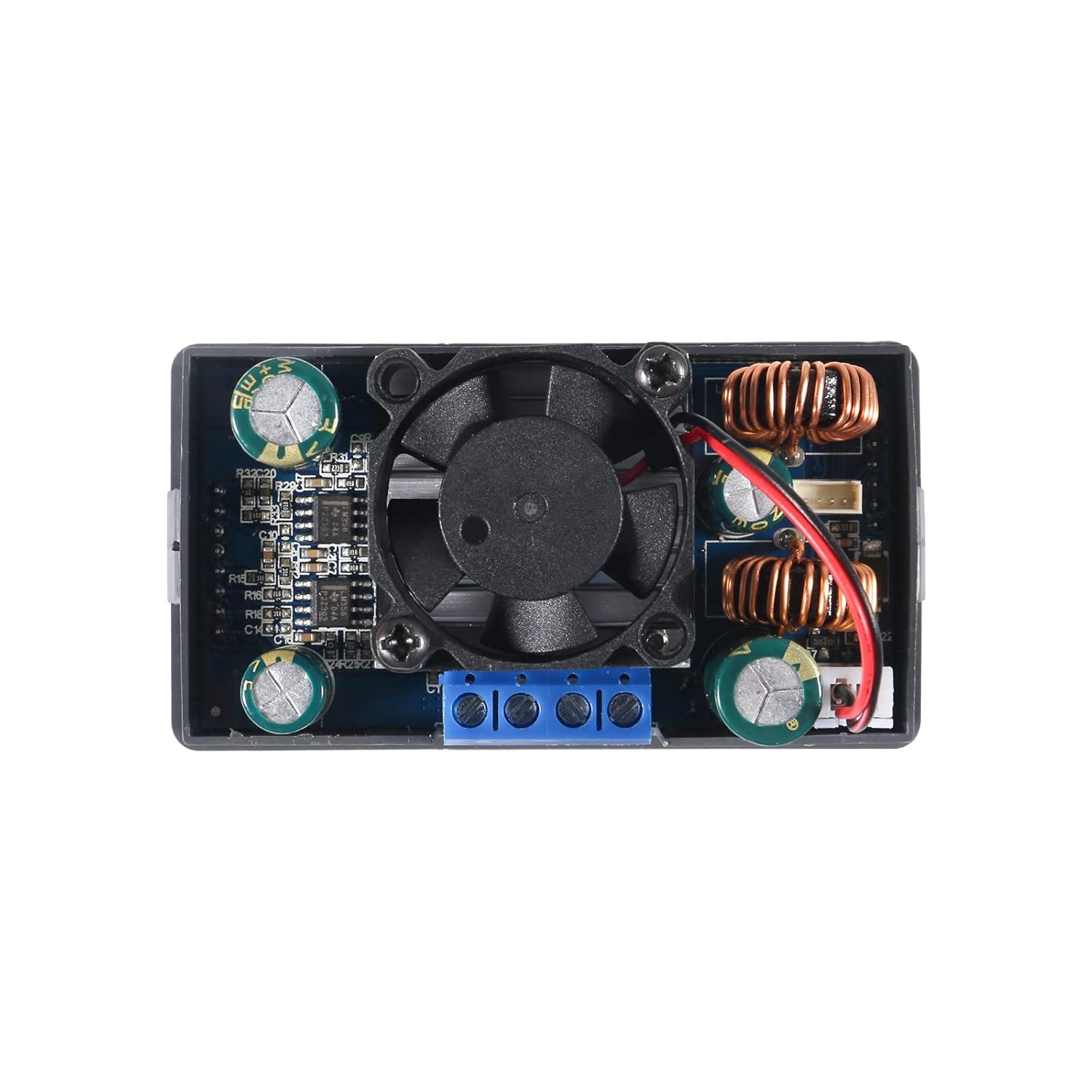
Figure 2: Rear View of the Converter. This image displays the rear side of the converter, highlighting the integrated cooling fan, inductors, capacitors, and other electronic components responsible for power conversion and regulation.

Figure 3: Converter Dimensions. This image provides the physical dimensions of the DORHEA Buck Boost Converter, including length, width, and height, useful for enclosure design and integration.
- Digital Display: Shows various operational parameters.
- Rotary Encoder Knob: Used for navigating menus and adjusting values.
- ON/OFF Button: Toggles output power.
- Input Terminals (VIN+/VIN-): Connect the DC input power source.
- Output Terminals (OUT+/OUT-): Connect the load.
- Cooling Fan: Activates automatically to dissipate heat during high load operation.
4. Setup
4.1 Wiring Connections
- Input Power Connection: Connect your DC power source (6V-36V) to the VIN+ (positive) and VIN- (negative) terminals. Ensure correct polarity.
- Load Connection: Connect your load to the OUT+ (positive) and OUT- (negative) terminals. Ensure correct polarity.
- Secure Connections: Use appropriate gauge wires and ensure all connections are tight to prevent loose contacts, which can lead to instability or damage. For stranded wires, twisting and tinning with solder is recommended for better contact in screw terminals.
4.2 Initial Power-Up
After wiring, apply power to the input terminals. The display should illuminate, showing the current input voltage and default output settings. The device is now ready for operation.
4.3 Panel Mounting (Optional)
The converter is designed for panel mounting. The cutout dimensions required for installation are approximately 72mm x 40mm, with a 12mm x 2.5mm notch centered on each narrow side for securing the unit.
5. Operating Instructions
5.1 Adjusting Output Voltage and Current
- Setting Mode: Press the rotary encoder knob to enter the setting mode. The parameter to be adjusted (voltage or current limit) will blink.
- Selecting Digits: Rotate the knob to move between digits or parameters.
- Changing Values: Press the knob to select a digit, then rotate to change its value. Press again to confirm the digit and move to the next.
- Exiting Setting Mode: After setting the desired voltage and current limit, wait a few seconds, and the display will return to the main interface, applying the new settings.
5.2 Output ON/OFF Control
Press the dedicated ON/OFF button (usually labeled with a circle and vertical line) to enable or disable the output power. When the output is off, the display will still show input parameters, but no power will be supplied to the load.
5.3 Display Modes and Customization
The converter offers multiple display pages and customization options:
- Parameter Display: Cycle through different display pages by short-pressing the rotary encoder knob (if not in setting mode). Pages include Voltage/Current/Power, Capacity/Energy/Time, and Voltage/Current graphs.
- System Settings: Long-press the rotary encoder knob to enter system settings. Here you can:
- Flip or rotate the display orientation.
- Change the background and parameter display colors.
- Switch between day and night display modes.
- Set various protection thresholds (OVP, OCP, OPP, LVP, OTP).
6. Maintenance
- Cleaning: Keep the device clean and free from dust. Use a soft, dry cloth for cleaning. Do not use liquids or abrasive cleaners.
- Ventilation: Ensure the cooling fan and ventilation openings are not obstructed to allow for proper heat dissipation.
- Heat Sink Inspection: Periodically check that the heat sink is securely attached and making good contact with the components it is designed to cool.
7. Troubleshooting
| Problem | Possible Cause | Solution |
|---|---|---|
| Output voltage is inaccurate or lower than set. | Calibration issue; measurement error; significant load causing voltage drop. | Verify output with a calibrated multimeter. Ensure the load is within the device's current limits. If persistent, contact support. |
| Device overheats quickly. | Excessive load; poor ventilation; improperly mounted heat sink. | Reduce load to stay within specified limits (e.g., 80W max). Ensure adequate airflow around the unit. Check heat sink contact. |
| Backlight turns off after a short period. | Display timeout setting. | Check system settings for display timeout options and adjust as needed. |
| Wires do not stay in screw terminals. | Improper wire preparation; incorrect wire gauge. | For stranded wire, twist and tin the ends with solder. For solid wire, ensure appropriate gauge. Bending the tip of smaller gauge solid wire into a loop can improve grip. |
| No display or power output. | No input power; incorrect wiring; device fault. | Check input power source. Verify all wiring connections for correct polarity and secure contact. If issues persist, contact support. |
8. Specifications
| Parameter | Value |
|---|---|
| Input Voltage Range | DC 6V - 36V |
| Output Voltage Range | DC 0.6V - 36V |
| Output Current Range | 0 - 5A (adjustable in 0.001A steps) |
| Output Power | Up to 80W (as advertised) |
| Voltage Adjustment Step | 0.01V |
| Current Adjustment Step | 0.001A |
| Protection Features | OVP, OCP, OPP, LVP, OTP, Reverse Protection, Short Circuit Protection |
| Dimensions (L x W x H) | Approximately 79mm x 43mm x 53mm (3.11 x 1.69 x 2.09 inches) |
| Panel Cutout Dimensions | 72mm x 40mm with 12mm x 2.5mm notches (approx.) |
| Item Weight | 3.84 ounces |
| Certifications | FCC, UL (as per specifications) |
9. Warranty and Support
For warranty information, technical support, or service inquiries, please contact DORHEA customer service through the retailer where the product was purchased. Please provide your product model number (3cf9aadc-ccbd-42cc-ba3e-50aa13bec481) and purchase details when contacting support.


