
Walfront XR2206
Walfront XR2206 Function Generator DIY Kit Instruction Manual
Adjustable Frequency Amplitude Sine Triangle Output
1. Introduction
Thank you for choosing the Walfront XR2206 Function Generator DIY Kit. This kit provides a versatile and easy-to-assemble solution for generating various waveforms, including sine, triangle, and square waves. It features adjustable frequency and amplitude, making it suitable for a wide range of electronic projects and educational purposes. This manual will guide you through the assembly process, operation, and maintenance of your new function generator.
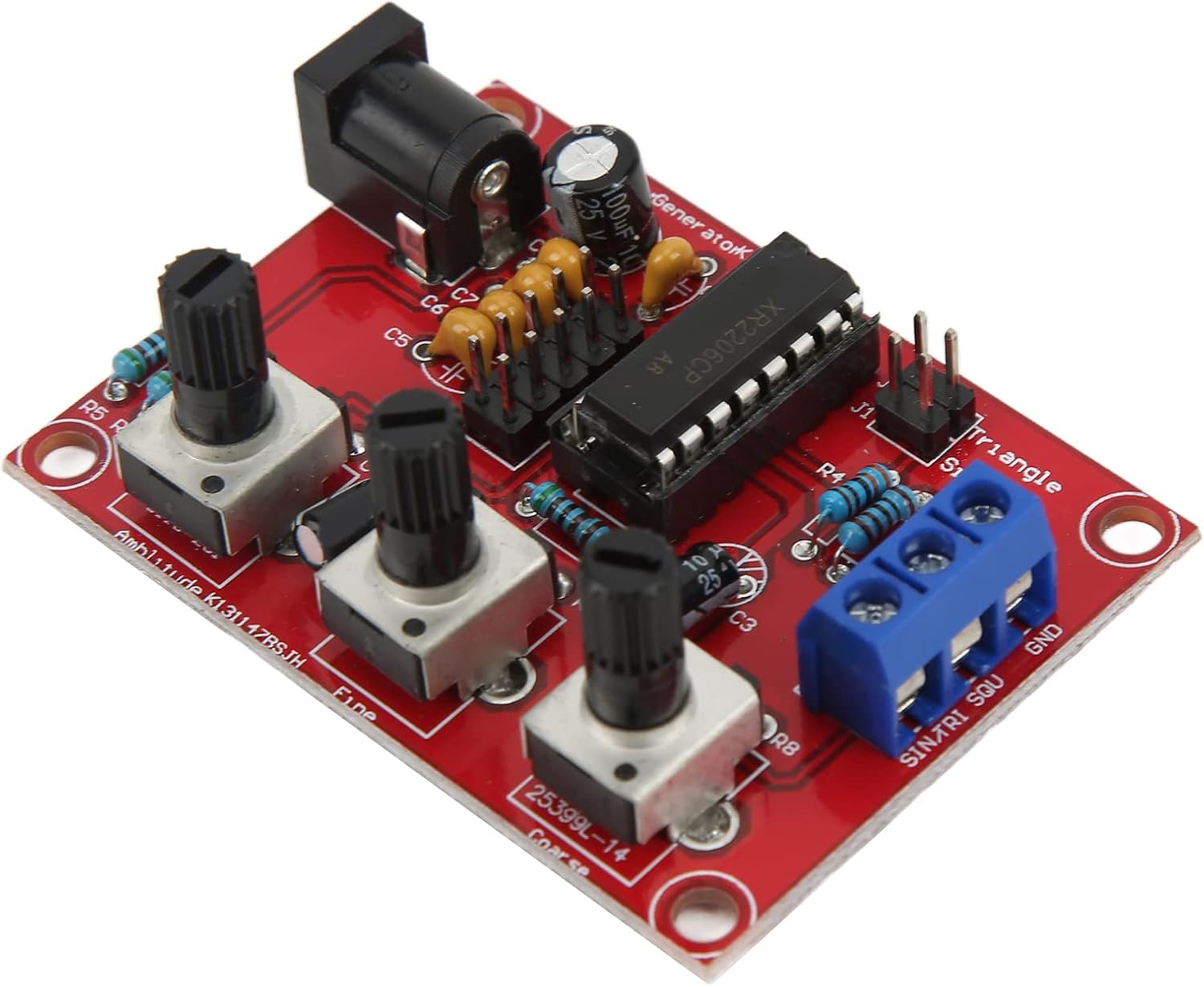
Image 1.1: The assembled XR2206 Function Generator circuit board.
2. Safety Information
Please read and understand all safety instructions before assembling and operating the device. Failure to follow these instructions may result in electric shock, fire, or serious injury.
- Power Supply: Only use a DC power supply within the specified voltage range of 9-12V. Using an incorrect voltage can damage the circuit.
- Soldering Safety: When soldering, ensure adequate ventilation. Wear appropriate personal protective equipment, such as safety glasses, to protect against solder splashes and fumes.
- Component Handling: Handle electronic components with care. Some components may be sensitive to static electricity.
- Sharp Edges: Be cautious of sharp edges on the PCB or enclosure parts during assembly.
- Children: Keep the kit and assembled device out of reach of children.
3. Package Contents
Verify that all components listed below are present in your package before beginning assembly. If any parts are missing or damaged, please contact customer support.
- 1 x XR2206 Function Generator PCB
- 6 x Enclosure Accessories (Acrylic/ABS panels)
- 3 x Knobs (for potentiometers)
- 9 x Screws
- 5 x Nuts
- 2 x Buckles (for enclosure assembly)
- 1 x User Manual (this document)
- Various electronic components (resistors, capacitors, diodes, IC socket, XR2206 IC, potentiometers, power socket, terminal block)

Image 3.1: Overview of all components included in the DIY kit.
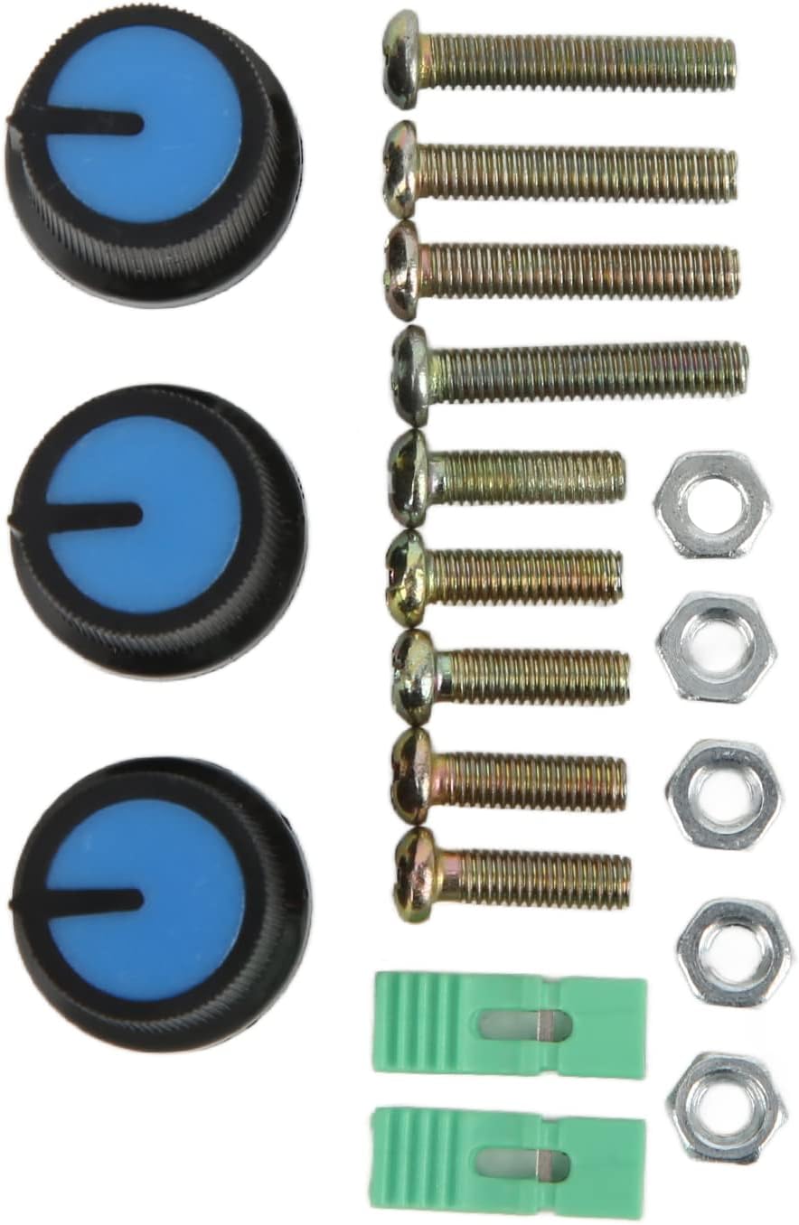
Image 3.2: Detailed view of the included hardware: knobs, screws, nuts, and buckles.
4. Assembly Instructions
The assembly process involves soldering various electronic components onto the Printed Circuit Board (PCB) and then assembling the enclosure. Follow these steps carefully:
4.1. Component Soldering
- Prepare the PCB: Ensure your workspace is clean, well-lit, and well-ventilated. Have your soldering iron, solder, desoldering wick/pump, and safety glasses ready.
- Solder Low-Profile Components First: Begin by soldering the lowest height components. This typically includes resistors, diodes, and small ceramic capacitors. Pay attention to the polarity of diodes (band indicates cathode).
- Solder Medium-Profile Components: Next, solder components like electrolytic capacitors (observe polarity, longer lead is positive), and the IC socket. Ensure the notch on the IC socket aligns with the marking on the PCB.
- Solder High-Profile Components: Finally, solder the power input jack, the terminal block (for output), and the adjustable potentiometers.
- Install XR2206 IC: Carefully insert the XR2206CP integrated circuit into its socket. Ensure the notch on the IC aligns with the notch on the socket and the PCB. Bend the pins slightly inward if necessary to fit.
- Trim Leads: After soldering each component, use diagonal pliers to carefully trim any excess component leads on the back of the PCB as short as possible to prevent short circuits and ensure a neat finish.
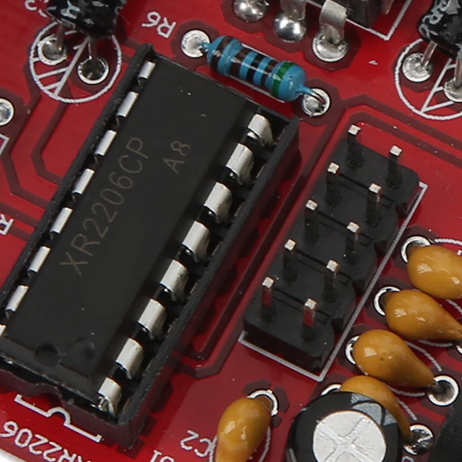
Image 4.1: Detailed view of the XR2206CP integrated circuit installed on the PCB.

Image 4.2: Close-up of the output terminal block (SINTRI SQU GND) and the potentiometers for adjustment.

Image 4.3: Underside of the PCB showing soldered component leads.
4.2. Enclosure Assembly
Once all components are soldered and leads are trimmed, assemble the protective enclosure using the provided acrylic/ABS panels, screws, nuts, and buckles.
- Identify Panels: Identify the top, bottom, and side panels. The top panel will have cutouts for the potentiometers, power jack, and terminal block.
- Mount PCB: Secure the PCB to the bottom panel using the appropriate screws and nuts.
- Attach Side Panels: Carefully attach the side panels, aligning them with the slots on the top and bottom panels.
- Secure Enclosure: Use the remaining screws, nuts, and buckles to firmly secure all panels together, forming the complete enclosure.
- Attach Knobs: Press the three plastic knobs onto the shafts of the potentiometers. Ensure they are firmly seated and aligned.
5. Operating Instructions
The XR2206 Function Generator is designed for ease of use, allowing for precise control over output frequency and amplitude.
5.1. Powering On
- Connect a 9-12V DC power adapter to the power input jack on the board.
- Ensure the power supply is stable and within the specified voltage range.
5.2. Output Connection
The output signals (Sine, Triangle, Square) and Ground (GND) are available on the blue terminal block. Connect your measurement device (e.g., oscilloscope, multimeter) or circuit to the appropriate terminals.
- SINTRI: Sine/Triangle wave output.
- SQU: Square wave output.
- GND: Ground reference.
5.3. Adjusting Frequency and Amplitude
The generator features three potentiometers for controlling the output:
- Frequency Coarse Adjustment: Use this knob for large changes in frequency.
- Frequency Fine Adjustment: Use this knob for precise, small adjustments to the frequency.
- Amplitude Adjustment: This knob controls the peak-to-peak voltage of the output waveform.
By combining the coarse and fine frequency adjustments, you can achieve a wide range of frequencies with 5-digit exactness resolution.
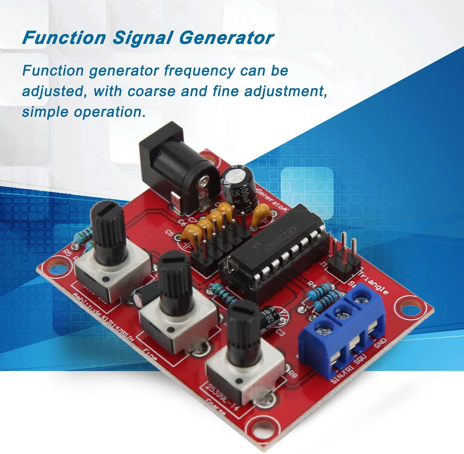
Image 5.1: The function generator highlighting its adjustable frequency feature.
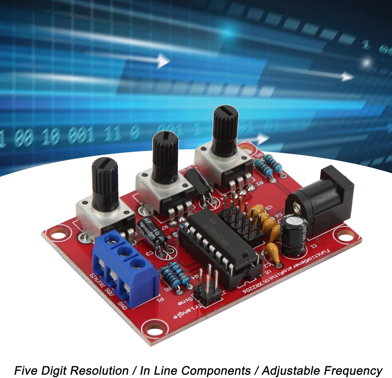
Image 5.2: Key features of the function generator: high resolution, in-line components, and adjustable frequency.

Image 5.3: The function generator is designed for simple operation and portability.
6. Specifications
| Feature | Specification |
|---|---|
| Model | XR2206 |
| Purpose | Function Generator |
| Voltage Supply | 9-12V DC Input |
| Output Waveforms | Sine, Triangle, Square |
| Frequency Adjustment | Coarse and Fine adjustment |
| Frequency Resolution | 5-digit exactness |
| Material | PCB, ABS |
| Item Weight | 3.87 ounces (approx. 110g) |
| Package Dimensions | 5.83 x 4.06 x 1.54 inches (approx. 14.8 x 10.3 x 3.9 cm) |
7. Troubleshooting
If you encounter issues with your function generator, consider the following common troubleshooting steps:
- No Output/Incorrect Waveform:
- Check all solder joints for cold joints or bridges. Re-solder if necessary.
- Verify component polarity (diodes, electrolytic capacitors, IC).
- Ensure the XR2206 IC is correctly seated in its socket and oriented correctly.
- Confirm the power supply is providing the correct voltage (9-12V DC) and is properly connected.
- Check connections to the output terminal block.
- Frequency/Amplitude Not Adjustable:
- Ensure the potentiometers are correctly soldered and not damaged.
- Check for any short circuits around the potentiometer pins.
- Device Not Powering On:
- Verify the power adapter is functional and providing power.
- Check the soldering of the DC power input jack.
If problems persist after checking these points, please refer to the support information provided.
8. Maintenance
The Walfront XR2206 Function Generator DIY Kit requires minimal maintenance once assembled.
- Cleaning: Keep the device clean and free from dust. Use a soft, dry cloth to wipe the enclosure. Avoid using liquid cleaners directly on the circuit board.
- Storage: Store the device in a dry, cool environment, away from direct sunlight and extreme temperatures.
- Handling: Avoid dropping the device or subjecting it to strong impacts, which could damage internal components or solder joints.
9. Warranty and Support
Walfront products are designed for quality and reliability. For specific warranty information, please refer to the terms and conditions provided at the time of purchase or contact your retailer.
For technical support, assembly assistance, or inquiries regarding missing/damaged parts, please contact Walfront customer service through the platform where you purchased the product. Please have your order number and product model (XR2206) ready when contacting support.
Related documentsXR2206

Ask a question about this manual
Ask about setup, troubleshooting, compatibility, parts, safety, or missing instructions. Manuals+ will review the question and use this page’s manual context to help answer it.