
1. Introduction
The Walfront MF47 Analog Multimeter is a versatile and reliable instrument designed for various electrical measurements. It is suitable for testing AC/DC voltage, DC current, and resistance. Featuring a clear dial with a carbon pointer tube to minimize bending errors, and a multi-range measurement capability, this multimeter is an essential tool for home appliance repair, scientific research, educational purposes, property maintenance, and general factory electrical work.
2. Safety Information
Always prioritize safety when using electrical testing equipment. Failure to follow these instructions may result in electric shock, fire, or damage to the meter or the equipment under test.
- Before making any measurement, ensure the multimeter's gear knob is set to the correct range for the expected value. Selecting an incorrect range can damage the device or cause injury.
- Do not exceed the maximum input ratings specified for each measurement function.
- Always disconnect power to the circuit before measuring resistance or continuity.
- Use extreme caution when working with live circuits. Avoid touching exposed conductors.
- Inspect test leads for damage before each use. Do not use if insulation is cracked or if the probes are exposed.
- Replace batteries promptly when the low battery indicator appears to ensure accurate readings.
- Do not operate the multimeter in wet environments or explosive atmospheres.
3. Product Overview
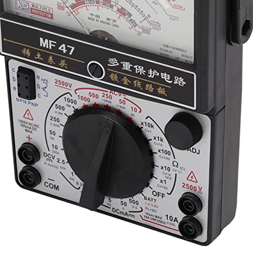
The Walfront MF47 Analog Multimeter features a robust design with clearly labeled components for ease of use. Familiarize yourself with the layout before operation.

Key Components:
- Support Frame: Provides stability and allows for angled viewing.
- Dial: Displays measurement readings with multiple scales for different functions.
- Zero Adjustment Knob: Used to set the pointer to zero before taking measurements, especially for resistance.
- Triode Test Jack: For testing transistors (NPN/PNP).
- Resistance/Voltage Input Terminal: Positive input for resistance and voltage measurements.
- Common Jack (COM): Negative input terminal for all measurements.
- Ohm Zeroing: Fine adjustment for resistance zeroing.
- Gear Knob: Rotary switch to select the desired measurement function and range.
- 2500V Voltage Jack: Dedicated input for high voltage measurements.
- DC 10A Jack: Dedicated input for high DC current measurements.
4. Specifications
The following table outlines the technical specifications and measurement ranges of the Walfront MF47 Analog Multimeter:

| Measurement Type | Limit Range | Sensitivity / Voltage Drop | Accuracy |
|---|---|---|---|
| DC Current | 0-0.5mA, 0-5mA, 0-50mA, 0-500mA, 10A (no fuse protection) | 0.25V | 2.5% (for mA ranges), 5% (for 10A) |
| DC Voltage | 0-0.25V, 0-1V, 0-2.5V, 0-10V, 0-50V, 0-250V, 0-500V, 0-1000V, 0-2500V | 20kΩ/V (for 0.25V-50V), 9kΩ/V (for 250V-2500V) | 2.5% |
| AC Voltage | 0-10V, 0-50V, 0-250V, 0-500V, 0-1000V, 0-2500V | 9kΩ/V | 5% |
| DC Resistance | Rx1, Rx10, Rx100, Rx1k, Rx10k, Rx100k | Center value 16.5 | 10% |
| On Off Beep | Continuity | Buzzer works when resistance is less than 50Ω | N/A |
Power Source: 1 x 9V 6F22 square battery or 1 x 1.5V LR20 battery (batteries not included).
5. Setup
5.1. Battery Installation
- Ensure the multimeter is turned OFF.
- Locate the battery compartment cover on the back of the unit.
- Carefully remove the cover.
- Insert one 9V 6F22 square battery and one 1.5V LR20 battery, observing the correct polarity (+/-) as indicated inside the compartment.
- Replace the battery compartment cover securely.
5.2. Connecting Test Leads
The multimeter comes with two test leads (red and black). Connect them to the appropriate jacks for your measurement type.

- Always connect the black test lead to the COM (Common) jack.
- For most voltage and resistance measurements, connect the red test lead to the Resistance/Voltage Input Terminal (usually marked with a '+' or 'VΩmA').
- For high DC current measurements (up to 10A), connect the red test lead to the DC 10A Jack.
- For very high voltage measurements (up to 2500V), connect the red test lead to the 2500V Voltage Jack.
6. Operating Instructions
Important: Always ensure the gear knob is set to the correct measurement function and range before connecting the test leads to a circuit. Incorrect settings can lead to damage or injury.
6.1. Measuring DC Voltage (DCV)
- Connect the black test lead to the COM jack and the red test lead to the Resistance/Voltage Input Terminal.
- Turn the gear knob to the desired DCV range. Start with the highest range if the voltage is unknown to prevent overload.
- Connect the test probes in parallel across the component or circuit where you want to measure voltage.
- Read the voltage value from the appropriate DCV scale on the dial.
6.2. Measuring AC Voltage (ACV)
- Connect the black test lead to the COM jack and the red test lead to the Resistance/Voltage Input Terminal.
- Turn the gear knob to the desired ACV range. Start with the highest range if the voltage is unknown.
- Connect the test probes in parallel across the AC voltage source or component.
- Read the voltage value from the appropriate ACV scale on the dial.
6.3. Measuring DC Current (DCmA/DC 10A)
- For mA ranges: Connect the black test lead to the COM jack and the red test lead to the Resistance/Voltage Input Terminal.
- For 10A range: Connect the black test lead to the COM jack and the red test lead to the DC 10A Jack.
- Turn the gear knob to the desired DCmA or DC 10A range. Start with the highest range if the current is unknown.
- Connect the multimeter in series with the circuit. This means breaking the circuit and inserting the multimeter so that the current flows through it.
- Read the current value from the appropriate DCmA scale on the dial.
6.4. Measuring Resistance (Ω)
- Ensure the circuit is completely de-energized before measuring resistance.
- Connect the black test lead to the COM jack and the red test lead to the Resistance/Voltage Input Terminal.
- Turn the gear knob to the desired resistance (Ω) range (e.g., Rx1, Rx10, Rx1k).
- Short the two test probes together. Use the Zero Adjustment Knob and Ohm Zeroing control to set the pointer exactly to zero on the resistance scale.
- Connect the test probes across the component whose resistance you want to measure.
- Read the resistance value from the appropriate Ω scale on the dial. Multiply the reading by the selected range multiplier (e.g., if on Rx100 range and pointer reads 50, the resistance is 50 x 100 = 5000Ω).
6.5. Continuity Test (On Off Beep)
- Ensure the circuit is de-energized.
- Connect the black test lead to the COM jack and the red test lead to the Resistance/Voltage Input Terminal.
- Turn the gear knob to an appropriate resistance range that includes the continuity function (often indicated by a speaker symbol or a low resistance range).
- Touch the test probes across the component or wire. If the resistance is less than 50Ω, the built-in buzzer will sound, indicating continuity.
7. Maintenance
7.1. Cleaning
Wipe the multimeter casing with a damp cloth. Do not use abrasive cleaners or solvents. Ensure the device is dry before storage or use.
7.2. Battery Replacement
When the multimeter's performance degrades or the pointer does not zero correctly, it may be time to replace the batteries. Follow the battery installation steps in Section 5.1.
7.3. Fuse Replacement
The MF47 Analog Multimeter is designed with internal double protection, likely referring to fuses. If the current measurement function stops working, a fuse may need replacement. Refer to a qualified technician for fuse replacement to ensure proper type and rating are used.
8. Troubleshooting
- No Reading / Incorrect Reading:
- Check if the gear knob is set to the correct function and range.
- Ensure test leads are securely connected to the correct jacks.
- Verify that the batteries are installed correctly and have sufficient charge.
- For resistance measurements, ensure the meter is zeroed correctly.
- Pointer Bending Error: This can occur due to overload. Always select a higher range first if the value is unknown.
- Meter Damage: If the meter was connected to a circuit with an incorrect range selected, it might be damaged. Discontinue use and seek professional repair.
9. Warranty and Support
For technical assistance, warranty claims, or product support, please contact Walfront customer service through the retailer where the product was purchased or visit the official Walfront website. Please have your product model (MF47) and purchase details available when contacting support.