
1. Introduction
This manual provides detailed instructions for the installation, operation, and maintenance of your TFCFL 110V 60W AC High Torque Gear Motor with Speed Controller. This single-phase electric motor is designed for applications requiring variable speed and reversible operation, offering stable performance and high torque.
1.1 Package Contents
Please verify that all components are present in the package:
- 1 x AC Gear Motor
- 1 x Gear Reducer
- 1 x Speed Controller

Figure 1.1: Main components of the TFCFL AC Gear Motor kit.
2. Safety Information
Always observe the following safety precautions to prevent injury or damage to the equipment:
- Ensure the power supply is disconnected before any installation, wiring, or maintenance procedures.
- This motor operates on 110V AC. Incorrect voltage can cause severe damage or electrical shock.
- All electrical connections should be made by a qualified professional in accordance with local electrical codes.
- Ensure proper grounding of the motor and speed controller to prevent electrical hazards.
- Do not operate the motor in wet or damp conditions.
- Keep hands and loose clothing away from moving parts during operation.
- Do not exceed the rated torque or speed of the motor.
3. Specifications
| Specification | Value |
|---|---|
| Brand | TFCFL |
| Model Name | gear |
| Rated Voltage | 110 Volts AC |
| Rated Power | 60 Watts |
| Rated Speed (Motor) | 1350 RPM (before reduction) |
| Output Speed (with 1:10 Reducer) | 0-135 RPM |
| Reduction Ratio | 1:10 (10K) |
| Torque | 3.8 Nm |
| Power Phase | Single-phase |
| Shaft Diameter | 12 mm |
| Motor Dimensions (L x W x H) | 139mm x 90mm x 74mm (approx. 5.47" x 3.54" x 2.91") |
| Reducer Dimensions (L x W x H) | 41mm x 90mm x 74mm (approx. 1.61" x 3.54" x 2.91") |
| Reversible | Yes |
| Material | Aluminum alloy, plastic |
| Item Weight | 10 Pounds |
Note: The output shaft speed varies with the deceleration ratio. The output shaft speed is calculated by dividing the motor speed (1350 rpm) by the deceleration ratio.

Figure 3.1: Motor and Reducer Dimensions.
4. Setup and Installation
Follow these steps to properly set up your AC gear motor:
4.1 Assembly of Motor and Reducer
- Carefully pull off the protective holster from the motor shaft before installation.
- Mount the gearbox (reducer) onto the motor, ensuring proper alignment.
- Secure the gearbox to the motor using the four provided screws. Tighten them firmly.
- Install the keyway into the keyway opening on the motor shaft.
4.2 Electrical Connections
WARNING: Ensure power is OFF before making any electrical connections.
- Connect the motor's main line to the speed controller's main line. Ensure the connectors are fully engaged.
- Unscrew the two AC screws on the back of the speed controller.
- Connect the single-phase 110V AC power supply to the two AC ports on the speed controller. These ports are not polarity-sensitive (not divided into live/neutral). Tighten the screws securely.
- Connect the ground wire (FG) from the speed controller to a suitable ground point. The motor also has a ground terminal; ensure it is properly grounded.

Figure 4.1: Wiring Procedure.

Figure 4.2: Wiring Diagram for Reversible Operation.
4.3 Mounting the Motor
If using a mounting bracket (not included), attach it to the motor using appropriate fasteners. Refer to the bracket dimensions for compatibility.
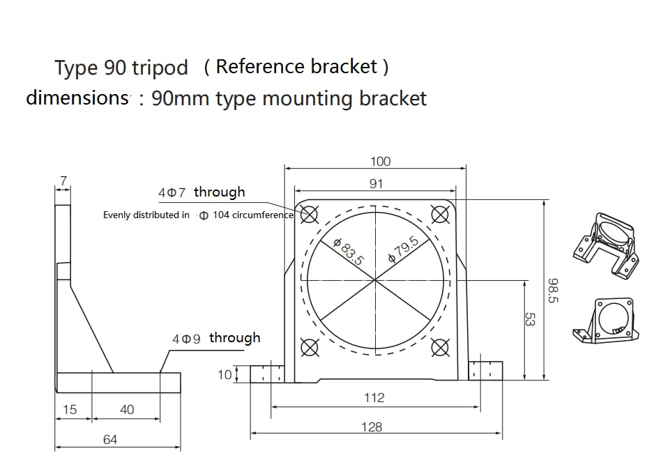
Figure 4.3: Reference Bracket Dimensions (Type 90 Tripod).
4.4 Visual Installation Guide
For a visual guide on the installation process, please watch the following video:
Video 4.1: Installation and Basic Operation of the TFCFL AC Gear Motor.
5. Operating Instructions
Once the motor and speed controller are correctly installed and wired, you can begin operation:
- Power On: Ensure the speed controller knob is set to the 'Low' position (fully counter-clockwise) before turning on the main power switch.
- Adjusting Speed: Turn the speed knob clockwise to increase the motor speed. Turn it counter-clockwise to decrease the speed. The indicator light on the controller will illuminate when power is supplied.
- Reversible Operation: The motor supports reversible rotation. To change the direction of rotation, use the switch on the speed controller. Always ensure the motor has come to a complete stop before changing direction to prevent damage.
- Power Off: To stop the motor, turn the speed knob to the 'Low' position and then switch off the main power.

Figure 5.1: Motor and Speed Controller.
6. Maintenance
Regular maintenance ensures the longevity and optimal performance of your motor:
- Cleaning: Keep the motor and speed controller free from dust, dirt, and debris. Use a soft, dry cloth for cleaning. Do not use liquids or solvents.
- Inspection: Periodically inspect all wiring connections for tightness and signs of wear or damage. Check the motor shaft for any obstructions.
- Ventilation: Ensure the motor's cooling fins and ventilation openings are clear to prevent overheating.
- Lubrication: The gearbox is typically pre-lubricated and sealed. Consult a qualified technician if lubrication is suspected to be an issue.
7. Troubleshooting
If you encounter issues with your motor, refer to the following common problems and solutions:
| Problem | Possible Cause | Solution |
|---|---|---|
| Motor does not start | No power supply; Loose wiring; Speed knob at 'Low' position; Overload. | Check power connection; Verify all wiring is secure; Turn speed knob clockwise; Reduce load on motor. |
| Motor runs intermittently | Loose connections; Faulty speed controller; Overheating. | Inspect and secure all wiring; Check for proper ventilation; Contact support if controller is suspected. |
| Incorrect speed or no speed control | Faulty speed controller; Incorrect wiring. | Verify wiring according to diagram; Test speed controller; Contact support. |
| Motor overheats | Insufficient ventilation; Excessive load; Prolonged operation at high load. | Ensure clear airflow around motor; Reduce load; Allow motor to cool down periodically. |
| Unusual noise or vibration | Loose mounting; Damaged bearings; Misalignment. | Check and tighten mounting bolts; Inspect for physical damage; Contact support. |
8. Warranty and Support
For warranty information or technical support, please contact TFCFL customer service through your purchase platform or the official TFCFL website. Please have your product model and purchase date available when contacting support.
