
1. Introduction
Thank you for choosing the FNIRSI-5012H Digital Oscilloscope. This device is a multifunctional, practical, and cost-effective handheld oscilloscope designed for a wide range of electrical signal measurements. It is an ideal tool for maintenance, research and development, and educational purposes.
The FNIRSI-5012H features a 2.4-inch IPS LCD display, a 100MHz analog bandwidth, and a maximum real-time sampling rate of 500MS/s, making it suitable for analyzing various signal types, including periodic analog signals, digital logic signals, and unexpected non-periodic signals.
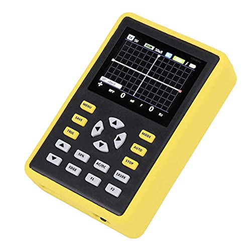
Figure 1.1: The FNIRSI-5012H Digital Oscilloscope, showing its compact design and clear display.
2. Product Features
- High Performance: 100MHz analog bandwidth and 500MS/s maximum real-time sampling rate.
- Versatile Trigger Modes: Includes Auto, Single, and Normal trigger modes to capture various signal types.
- Single Trigger Mode: Ideal for testing unexpected non-periodic signals, such as car ignition signals.
- Normal Trigger Mode: Suitable for testing digital logic signals, like infrared remote control signals.
- Auto Trigger Mode: Best for testing periodic analog signals, such as sine waves.
- Wide Application: Nearly universal for electrical signal measurement in fields such as amplifiers, oscillators, automatic control systems, DC/DC conversion, inverter systems, and switching power supplies.
- User-Friendly Display: Equipped with a 2.4-inch 320x240 IPS LCD display for clear waveform visualization.
- Portable Power: Powered by a 5000 mAh lithium battery for extended use on the go.
- Waveform Storage: Features 128kb storage depth for capturing and reviewing waveforms.
3. Setup
3.1 Unpacking and Inspection
Upon receiving your FNIRSI-5012H Digital Oscilloscope, carefully unpack all components and inspect them for any signs of damage. If any items are missing or damaged, please contact your vendor immediately.

Figure 3.1: The oscilloscope and its accessories neatly stored in the provided carrying case.
3.2 Charging the Device
Before first use, ensure the oscilloscope is fully charged. Connect the provided USB charging cable to the device's charging port and a suitable USB power adapter (not included). The charging indicator will show the charging status.
3.3 Connecting the Probe
The oscilloscope comes with a test probe. To connect it:
- Locate the BNC connector on the top of the oscilloscope.
- Align the probe's BNC connector with the oscilloscope's connector.
- Push and twist the probe's connector clockwise until it locks securely into place.
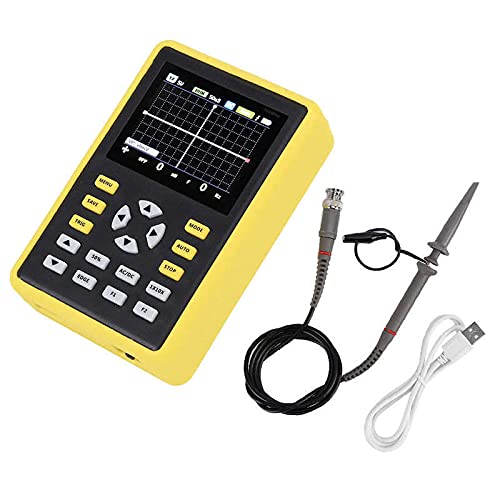
Figure 3.2: The FNIRSI-5012H oscilloscope shown with its test probe and USB charging cable.
4. Operating Instructions
4.1 Power On/Off
To power on the device, press and hold the power button (usually located on the side or front panel) until the display illuminates. To power off, press and hold the same button until the display turns off.
4.2 Basic Measurement
After powering on, the oscilloscope will display a grid and waveform area. Connect the probe to the circuit you wish to measure. The display will show the waveform of the signal.

Figure 4.1: The FNIRSI-5012H oscilloscope actively measuring a signal on a circuit board, demonstrating its practical application.
4.3 Adjusting Settings
Use the navigation buttons and dedicated function buttons (e.g., MENU, SAVE, TRIG, MODE, AUTO, STOP, 50%, AC/DC, EDGE, 1X/10X) to adjust measurement parameters:
- Vertical Sensitivity (V/div): Adjusts the vertical scale to fit the waveform on the screen. Use the appropriate buttons (often labeled with up/down arrows or dedicated V/div controls).
- Horizontal Time Range (S/div): Adjusts the horizontal scale to view more or less of the waveform over time.
- Trigger Mode: Select between Auto, Single, or Normal modes using the MODE button to stabilize the waveform display.
- Trigger Edge: Use the EDGE button to select between rising or falling edge triggering.
- Coupling Mode (AC/DC): Use the AC/DC button to switch between AC coupling (blocks DC component) and DC coupling (shows total signal).
- Probe Attenuation (1X/10X): Ensure the probe's attenuation setting (e.g., 1X or 10X) matches the setting on the oscilloscope (use the 1X/10X button) for accurate readings.
- Auto-Adjust: Press the AUTO button for the oscilloscope to automatically adjust vertical and horizontal settings to display a stable waveform.
- Waveform Storage: Use the SAVE button to store the current waveform for later review.
5. Maintenance
Proper maintenance ensures the longevity and accuracy of your FNIRSI-5012H Digital Oscilloscope.
- Cleaning: Use a soft, dry cloth to clean the device. For stubborn dirt, a slightly damp cloth with mild detergent can be used, but ensure no liquid enters the device. Do not use abrasive cleaners or solvents.
- Storage: When not in use, store the oscilloscope and its accessories in the provided storage bag in a cool, dry place, away from direct sunlight, extreme temperatures, and high humidity.
- Battery Care: To maintain battery health, avoid fully discharging the battery frequently. If storing for a long period, charge the battery to about 50% every few months.
- Probe Care: Handle the test probe carefully. Avoid bending or stressing the cable and connector. Keep the probe tip clean.
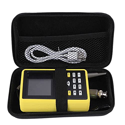
Figure 5.1: The FNIRSI-5012H oscilloscope and its accessories, including the USB cable and probe, securely stored in the protective carrying case.
6. Troubleshooting
This section provides solutions to common issues you might encounter with your oscilloscope.
| Problem | Possible Cause | Solution |
|---|---|---|
| Device does not power on. | Low battery or no charge. | Connect the USB charging cable and charge the device for at least 30 minutes. |
| No waveform displayed or waveform is unstable. | Incorrect probe connection, wrong trigger settings, or signal too weak/strong. | Ensure probe is securely connected. Press AUTO button. Adjust Vertical Sensitivity (V/div) and Horizontal Time Range (S/div). Check Trigger Mode (Auto, Single, Normal) and Trigger Edge. |
| Waveform is distorted or noisy. | Improper grounding, external interference, or incorrect probe attenuation. | Ensure proper grounding of the circuit. Minimize external electromagnetic interference. Verify probe attenuation (1X/10X) matches oscilloscope setting. |
| Buttons are unresponsive. | Device frozen or software issue. | Try restarting the device by holding the power button. If issue persists, contact customer support. |
7. Specifications
| Parameter | Value |
|---|---|
| Item Type | Digital Oscilloscope |
| Model | FNIRSI-5012H |
| Material | Engineering Plastic |
| Analog Bandwidth | 100MHz |
| Max Real-time Sampling Rate | 500MS/s |
| Vertical Sensitivity | 50 mV/div ~ 100 V/div |
| Horizontal Time Range | 50S/div ~ 6nS/div |
| Max Test Voltage | 80V (1x probe), 800V (10x probe) |
| Storage Depth | 128 kb |
| Input Resistance | 1MΩ |
| ADC Accuracy | 8-bit |
| Coupling Mode | AC / DC |
| Trigger Mode | Single, Normal, Auto |
| Trigger Edge | Rising / Falling edge |
| External Trigger Voltage | 0-80V |
| Display | 2.4 inch - 320 x 240 - IPS process |
| Power Supply | 5000 mAh Lithium Battery |
8. Package Contents
The standard package for the FNIRSI-5012H Digital Oscilloscope includes the following items:
- 1 x FNIRSI-5012H Digital Oscilloscope
- 1 x USB Charging Cable
- 1 x Test Probe (Test Line)
- 1 x User Manual (this document)
- 1 x Storage Bag
9. Warranty and Support
For warranty information and technical support, please refer to the contact details provided by your retailer or visit the official Lufasa website. Keep your purchase receipt as proof of purchase for warranty claims.


