
1. Introduction
This manual provides essential information for the proper use and operation of the DIYElectronic STM32F405RG Development Board. The STM32F405RG is an ARM STM32F4 JTAG/SWD programmable MCU controller system board, designed for various embedded development projects. It features a built-in W25Q16 download chip, allowing direct code downloads, and exposes all pins for flexible interface resource utilization.

Figure 1: Top-down view of the STM32F405RG Development Board, showcasing its compact design and various components.
2. Features
- Support for USB one-key download.
- Compatibility with 1.44 and 1.8 inch TFT LCD screens.
- Support for OLED LCD screens.
- Equipped with General Purpose Input/Output (GPIO) pins.
- Includes a work LED indicator for operational status.
3. Specifications
| Product Name | STM32F405RG Development Board |
| Work Voltage | DC 5V/3.3V |
| Controller IC | STM32F405RG (STMicroelectronics Cortex-M4) |
| Operating Temperature | -20℃ ~ 85℃ |
| Operating Humidity | 5% ~ 95% RH |
| Module Size | 67mm * 54mm * 14mm |
| Connectivity Technology | GPIO |

Figure 2: Physical dimensions of the development board, illustrating its length, width, and height.
4. Package Contents
The following items are included in your product package:
- 1x STM32F405RG Development Board
- 1x 20cm Dupont Line
- 1x 80cm USB Data Cable
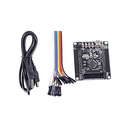
Figure 3: Image showing the STM32F405RG Development Board along with the included Dupont line and USB data cable.
5. Board Layout and Pinout
Understanding the layout of the development board is crucial for proper connection and programming. The board features various interfaces and indicators as detailed below.
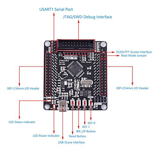
Figure 4: Detailed diagram indicating the location of key components such as the USART1 Serial Port, JTAG/SWD Debug Interface, OLED/TFT Screen Interface, Boot Mode Jumper, 30P-2.54mm I/O Headers, LED Status Indicator, LED Power Indicator, USB-Slave Interface, Reset Button, WK_UP Button, KEY 0, and KEY 1.
- USART1 Serial Port: For serial communication.
- JTAG/SWD Debug Interface: For programming and debugging the MCU.
- OLED/TFT Screen Interface: Dedicated header for connecting compatible display modules.
- Boot Mode Jumper: Used to select the boot mode of the STM32F405RG microcontroller.
- 30P-2.54mm I/O Headers: Provide access to the microcontroller's GPIO pins.
- LED Status Indicator: Indicates various operational states.
- LED Power Indicator: Illuminates when the board is powered.
- USB-Slave Interface: For connecting the board to a host computer for power and data transfer.
- Reset Button: Resets the microcontroller.
- WK_UP Button, KEY 0, KEY 1: User-programmable buttons.
6. Setup Instructions
Follow these steps to set up your STM32F405RG Development Board:
- Power Connection: Connect the provided USB data cable to the USB-Slave Interface on the development board and to a USB port on your computer or a 5V power adapter. The LED Power Indicator should illuminate.
- Driver Installation: Depending on your operating system, you may need to install specific USB drivers for the STM32 microcontroller. Refer to STMicroelectronics' official website for the latest driver packages (e.g., ST-Link drivers if using an external programmer, or DFU drivers for USB bootloader).
- Development Environment Setup: Install a suitable Integrated Development Environment (IDE) such as Keil MDK-ARM, IAR Embedded Workbench, or STM32CubeIDE. Ensure that the necessary toolchains and compilers for ARM Cortex-M4 are installed.
- Programming Method:
- USB One-Key Download: Utilize the built-in W25Q16 download chip for direct code downloads via the USB interface. Specific software tools (e.g., STM32 Flash Loader Demonstrator or custom tools) may be required.
- JTAG/SWD Debug Interface: For advanced debugging and programming, connect an external programmer/debugger (e.g., ST-Link V2/V3, J-Link) to the JTAG/SWD Debug Interface.
- Initial Test: Load a simple "blink" LED program to verify the board's functionality and your development environment setup.
7. Operating Instructions
Once the development environment is set up, you can begin programming and interacting with the STM32F405RG Development Board.
- Code Development: Write your embedded C/C++ code using your chosen IDE. Utilize the STM32CubeMX tool for easy configuration of peripherals and pin assignments.
- Compiling and Building: Compile your source code into an executable binary (e.g., .hex or .bin file) using the IDE's build tools.
- Flashing the Firmware:
- Via USB: If using the one-key download feature, follow the instructions for your specific download tool to transfer the firmware to the board.
- Via JTAG/SWD: Connect your external programmer/debugger and use the IDE's integrated flashing utility or a standalone programmer software (e.g., STM32 ST-LINK Utility) to upload the firmware.
- Debugging: For debugging, connect your external debugger to the JTAG/SWD interface. Use the IDE's debugger to set breakpoints, step through code, inspect variables, and monitor registers.
- Peripheral Interfacing: Connect external modules (e.g., TFT/OLED screens, sensors, actuators) to the appropriate GPIO headers or dedicated interfaces as per your project requirements. Ensure correct voltage levels and pin configurations.
8. Maintenance
Proper care and maintenance will ensure the longevity and reliable operation of your development board.
- Storage: Store the board in an anti-static bag when not in use to prevent electrostatic discharge (ESD) damage. Keep it in a dry environment, away from direct sunlight and extreme temperatures.
- Cleaning: If necessary, gently clean the board with a soft, dry brush or compressed air to remove dust. Avoid using liquids or abrasive cleaners.
- Handling: Always handle the board by its edges to minimize contact with components and prevent ESD.
- Power Supply: Ensure that the power supply voltage (DC 5V/3.3V) is within the specified range to prevent damage to the microcontroller and other components.
9. Troubleshooting
If you encounter issues with your STM32F405RG Development Board, consider the following troubleshooting steps:
- Board Not Powering On:
- Check the USB cable connection.
- Verify the power source (USB port or adapter) is providing 5V.
- Ensure the LED Power Indicator is lit. If not, try a different USB cable or power source.
- Unable to Upload Code:
- Confirm that the correct drivers are installed on your computer.
- Check the boot mode jumper settings. For programming, it typically needs to be set to boot from Flash memory or System memory (for DFU).
- Verify the connection to your programmer/debugger (JTAG/SWD) or the USB cable for one-key download.
- Ensure your IDE or programming software is correctly configured for the STM32F405RG microcontroller.
- Try resetting the board using the Reset button.
- Peripheral Not Working:
- Double-check your wiring connections to the GPIO headers.
- Review your code for correct pin initialization and peripheral configuration.
- Ensure the external peripheral is powered correctly and compatible with the board's voltage levels.
- Board Becomes Unresponsive:
- Perform a hard reset by disconnecting and reconnecting power.
- If a program is causing issues, try entering DFU mode (Device Firmware Upgrade) to re-flash a known working firmware.
10. Warranty and Support
This DIYElectronic product is designed for educational and development purposes. While specific warranty details are not provided in this manual, standard consumer rights and return policies apply as per the point of purchase. For technical support, documentation, and community forums, please refer to the official STMicroelectronics website for the STM32F4 series microcontrollers, and the DIYElectronic vendor for product-specific inquiries.
Always ensure you are using the latest software tools and drivers for optimal performance and compatibility.

