
1. Introduction
The ZK-PP2K signal generator is a versatile device designed to produce electrical signals with adjustable frequency, square wave, and pulse characteristics. It supports dual operation modes: PWM (Pulse Width Modulation) mode and PULSE mode. This module features high current output capability, allowing direct connection to motors or lamps. It serves as a signal or excitation source for various testing and practical applications in production and technology.
2. Features
- Dual operating modes: PWM mode and PULSE mode.
- High-definition LCD display for clear parameter viewing.
- Adjustable frequency control.
- Adjustable duty cycle control.
- High precision signal generation.
- Power-down memory function retains settings.
- Single-channel signal output.
- Reverse polarity protection.
- Enabled/disabled output control.
- Direct drive capability for LEDs, motors, and solenoid valves.
3. Specifications
| Product Name | ZK-PP2K PWM Signal Generator |
| Model | ZK-PP2K |
| Work Voltage | DC 3.3V-30V |
| Frequency Range | 1Hz~150KHz |
| Frequency Accuracy | 2% |
| Duty Cycle Range | 0.00%-100% |
| Output Current | 8A (Max) |
| Number of Pulses | 1~9999 or Infinite |
| Delay Time | 0.000s~9999s |
| Pulse Width | 0.000s~9999s |
| Time Accuracy | 1ms |
| Output Amplitude | Same as input voltage |
| Work Temperature | -20℃~85℃ |
| Work Humidity | 0%~95%RH |
| Dimensions | 79mm * 43mm * 26mm |

4. Setup and Wiring
Proper connection of the power supply and output is crucial for the safe and correct operation of the ZK-PP2K module. Refer to the wiring diagram below for guidance.
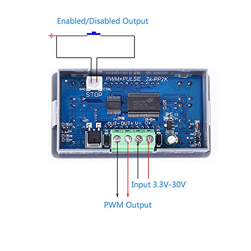
- Power Input: Connect a DC power source (3.3V to 30V) to the designated input terminals (V+ and V-). Ensure correct polarity.
- PWM Output: Connect your load (motor, lamp, solenoid valve) to the PWM output terminals (OUT+ and OUT-).
- Enabled/Disabled Output Control: An external switch can be connected between the CTRL pin and GND to enable or disable the output signal.
5. Operation
The ZK-PP2K operates in two primary modes: PWM Mode and PULSE Mode. The device features an LCD display and several buttons for configuration.

5.1. Button Functions
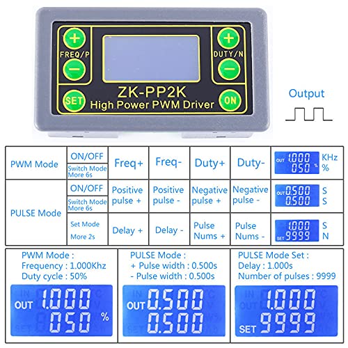
- FREQ+ / FREQ-: Adjusts frequency in PWM mode, or positive pulse width in PULSE mode.
- DUTY+ / DUTY-: Adjusts duty cycle in PWM mode, or negative pulse width in PULSE mode.
- SET: Used to switch between parameters for adjustment (e.g., frequency, duty cycle, pulse count, delay). Long press to switch between PWM and PULSE modes.
- ON: Toggles the output signal on or off.
5.2. Work Modes
The ZK-PP2K supports two distinct operating modes:
5.2.1. PWM Mode
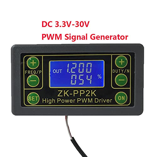
This mode is indicated by a '%' symbol on the LCD display. It is the factory default mode.
- Frequency Adjustment: Use the FREQ+ and FREQ- buttons to set the output frequency. Short presses adjust in minimum units, while holding the button allows for continuous adjustment. The frequency range is 1Hz to 150KHz.
- Duty Cycle Adjustment: Use the DUTY+ and DUTY- buttons to set the output duty cycle. Short presses adjust in minimum units, holding the button allows for continuous adjustment. The duty cycle range is 0.00% to 100%.
- Output Control: Short press the ON button to enable or disable the output signal.
5.2.2. PULSE Mode
To switch to PULSE mode, long press the SET button for more than 2 seconds. In PULSE mode, the display will show pulse width and number of pulses or delay time.
- Positive Pulse Width: Use FREQ+ and FREQ- buttons to adjust the positive pulse width.
- Negative Pulse Width: Use DUTY+ and DUTY- buttons to adjust the negative pulse width.
- Delay Time and Pulse Count: Use the SET button to cycle through parameters like delay time and number of pulses. Adjust these values using the FREQ+/FREQ- and DUTY+/DUTY- buttons as appropriate.
6. Maintenance
To ensure the longevity and optimal performance of your ZK-PP2K module, follow these maintenance guidelines:
- Cleaning: Keep the module clean and free from dust and debris. Use a soft, dry cloth for cleaning. Avoid using liquid cleaners or solvents.
- Storage: Store the module in a dry environment, away from extreme temperatures and humidity.
- Handling: Handle the module with care to prevent physical damage to the components or connections.
- Power Supply: Always use a stable power supply within the specified voltage range (DC 3.3V-30V) to prevent damage.
7. Troubleshooting
If you encounter issues with your ZK-PP2K module, consider the following common troubleshooting steps:
- No Power/Display:
- Check the power supply connections for correct polarity and secure contact.
- Verify that the input voltage is within the specified range (DC 3.3V-30V).
- Ensure the power supply is functioning correctly.
- No Output Signal:
- Confirm that the output is enabled by pressing the 'ON' button.
- Check the output wiring to the load for secure connections.
- Verify that the load (motor, lamp) is functioning correctly and not drawing excessive current.
- Ensure the module is not in a disabled state via the CTRL pin if an external switch is used.
- Incorrect Frequency/Duty Cycle:
- Ensure you are in the correct operating mode (PWM or PULSE).
- Re-adjust the frequency/duty cycle using the respective buttons.
- Check for any external interference that might affect signal generation.
If problems persist, please contact DIYElectronic customer support for further assistance.
8. Warranty and Support
DIYElectronic products are designed for reliability and performance. For specific warranty information, please refer to the purchase documentation or the official DIYElectronic website. For technical support, troubleshooting assistance, or inquiries regarding your ZK-PP2K module, please contact our customer service department through the vendor from whom you purchased the product or visit the official DIYElectronic support channels.
Please have your product model (ZK-PP2K) and purchase details ready when contacting support.