
1. Introduction
The DIYElectronic RCN-1 is a DC 9V-12V Infrared Remote Control DIY Kit designed for assembling an LED lamp. This kit allows users to construct a lamp featuring 18 white LEDs, controllable via any standard infrared remote controller. It also includes a dual-brightness control function.
2. Product Features
- Equipped with 18 high-brightness white LEDs.
- Simple circuit design, ideal for DIY enthusiasts.
- Two-position brightness control for varied illumination.
- Designed for hand soldering assembly.
- Infrared remote control capability for convenient operation.
3. Specifications
| Parameter | Value |
|---|---|
| Product Name | RCN-1 IR Control Lamp DIY Kit |
| Product Number | RCN-1 |
| Work Voltage | DC 9V-12V |
| Work Current | 30mA |
| Power Type | 5.5mm Power Socket or 9V Battery (Not Included) |
| Work Mode | Switch or Infrared Remote Control |
| LED Color | White |
| Work Temperature | -40℃ ~ 85℃ |
| Work Humidity | 5% ~ 85%RH |
| Dimensions (Installed) | 65mm * 65mm * 36mm |
4. Setup and Assembly Instructions
This product is a DIY kit and requires assembly by the user. Please follow these guidelines carefully:
- Preparation: Ensure you have all necessary welding tools before beginning assembly.
- Patience: Take your time during installation. Rushing can lead to errors or damage.
- Component Handling: When soldering, avoid prolonged contact of the soldering iron with components (limit to approximately 1.0 second) to prevent damage.
- Polarity: Pay close attention to the positive and negative terminals of components, especially LEDs and electrolytic capacitors, to ensure correct orientation.
- Short Circuits: Strictly prohibit any short circuits during assembly and operation.
- LED Installation: Install the LEDs according to the markings on the PCB and the circuit diagram.
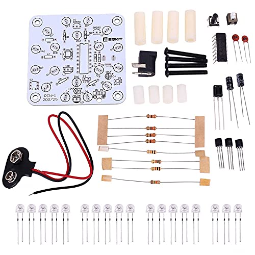
Image 1: All components included in the RCN-1 DIY kit, laid out before assembly. This includes the PCB, various resistors, capacitors, LEDs, switches, ICs, and power connectors.
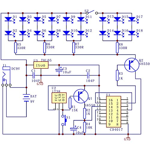
Image 2: Detailed circuit diagram for the RCN-1 Infrared Remote Control Lamp. This diagram illustrates the connections for the LEDs, control IC (CD4017), transistors, resistors, capacitors, and power input.
5. Operating Instructions
Once assembled, the RCN-1 lamp can be operated using its onboard controls or an infrared remote control.
5.1. Power Connection
Connect a DC 9V-12V power source to the 5.5mm power socket on the assembled board. Alternatively, a 9V battery can be connected (battery not included).
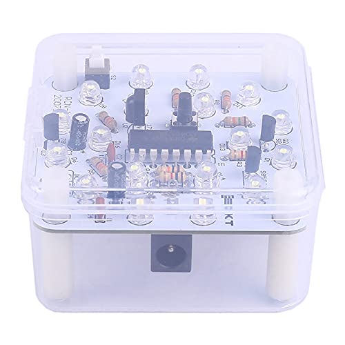
Image 3: Rear view of the assembled RCN-1 unit within its protective casing, showing the 5.5mm power input socket.
5.2. Onboard Controls
- S1 Black Button: This button is used to manually turn the lamp ON or OFF. Press once to toggle the power state.
- S2 Self-Locking Switch: This switch controls the LED brightness.
- In one position, 12 LEDs will illuminate.
- In the other position, all 18 LEDs will illuminate, providing maximum brightness.
5.3. Infrared Remote Control
Any standard infrared remote controller can be used to turn the lamp ON or OFF. Point the remote at the IR receiver on the RCN-1 board and press any button to toggle the lamp's power state.

Image 4: Top view of the fully assembled RCN-1 circuit board, showcasing the 18 white LEDs, the S1 black button, the S2 self-locking switch, and the infrared receiver.

Image 5: Angled view of the assembled RCN-1 unit enclosed in its transparent protective casing, demonstrating its compact form factor.
6. Maintenance
The RCN-1 kit is designed for durability, but proper care ensures longevity:
- Cleaning: Keep the circuit board and casing free from dust and debris. Use a soft, dry cloth for cleaning. Avoid liquid cleaners.
- Power Supply: Always use a stable DC 9V-12V power supply. Incorrect voltage can damage components.
- Environmental Conditions: Operate the device within the specified temperature and humidity ranges (-40℃~85℃, 5%~85%RH) to prevent malfunction.
- Physical Damage: Avoid dropping or subjecting the unit to strong impacts, which can loosen or break soldered connections.
7. Troubleshooting
If you encounter issues with your RCN-1 kit, consider the following troubleshooting steps:
- Lamp Does Not Turn On:
- Verify the power supply is connected correctly and providing 9V-12V DC.
- Check all soldered connections for cold joints or bridges.
- Ensure LEDs are installed with correct polarity.
- Confirm the S1 button or IR remote signal is being received.
- Incorrect Brightness:
- Check the position of the S2 self-locking switch.
- Inspect the connections to the LEDs and the brightness control circuit.
- Remote Control Not Working:
- Ensure the IR receiver component is correctly installed and oriented.
- Confirm your remote control is functioning and has fresh batteries.
- Test with a different IR remote control if available.
- Flickering LEDs:
- Check for loose connections or faulty solder joints.
- Verify the power supply is stable and not fluctuating.
If problems persist after these steps, carefully re-examine the circuit diagram and all component placements and connections.
8. Application Examples
The RCN-1 kit serves multiple purposes beyond just a functional lamp:
- Educational Tool: Excellent for training welding skills and for student school projects.
- DIY Production: Suitable for personal DIY electronic projects.
- Electronic Competitions: Can be used as a component or a complete project in electronic competitions.
- Project Design: A practical module for integrating into larger electronic designs.
9. Warranty and Support
Information regarding specific warranty terms or direct customer support for the DIYElectronic RCN-1 kit is not provided in the available product data. For assistance, please refer to the retailer or platform where the kit was purchased.