1. Introduction
This manual provides essential information for the safe and efficient operation of your HKS VFD 7.5KW 10HP 220V Variable Frequency Drive. Please read this manual thoroughly before installation, operation, or maintenance to ensure proper usage and prevent potential hazards.
The HKS VFD is designed for precise motor speed control in various industrial applications, including CNC machines, spindle motors, compressors, and grinders. It supports both single-phase and three-phase 220V input and provides three-phase 220V output with a frequency range of 0-400Hz.
2. Safety Information
WARNING: Electrical shock hazard. Only qualified personnel should perform installation and maintenance.
- Ensure power is disconnected before any wiring or maintenance.
- Verify correct voltage and current ratings before connecting the VFD.
- Do not connect AC power to the output terminals (U, V, W).
- Discharging time is greater than 5 seconds after power-off. Wait for the indicator to turn off before touching components.
- The inside of the heat sink may reach about 176°F (80°C) when the VFD is working. Exercise caution.
- Do not install any switch between the VFD and the load. Refer to the wiring diagram for proper switch implementation.
- Select a VFD model with a power rating at least 15% greater than the load for heavy-duty applications.
- Ensure your motor is a 3-phase asynchronous motor before purchasing and connecting.
3. Product Overview
3.1. Key Features
- Power: 7.5KW (10HP)
- Input Voltage: AC 220V (180-250V), 1-phase or 3-phase
- Output Voltage: 220V, 3-phase
- Input Current: 35A
- Output Current: 50A
- Input Frequency: 40-60HZ
- Output Frequency: 0-400HZ
- Intuitive display and control buttons.
- Detachable control panel for remote operation.
- Multiple protection features: overload, fuse, overvoltage, undervoltage, restart, stall, short circuit, and overheat protection.
- Low noise and electromagnetic interference due to PMW control technology and optimized cooling design.
3.2. Dimensions
The HKS VFD 7.5KW 10HP 220V unit has approximate dimensions of 5 x 5 x 5 inches and weighs 6.45 pounds.

Figure 3.2.1: HKS VFD unit with indicated dimensions (5.9in x 7.1in x 8.7in, note: image dimensions differ slightly from product specifications, refer to text for official dimensions).

Figure 3.2.2: The HKS VFD features a detachable control panel for flexible installation and remote control capabilities.
4. Installation
4.1. Wiring Connections
Ensure all power is disconnected before proceeding with wiring. The VFD has terminals for input power (R, S, T) and output to the motor (U, V, W).
- For 3-phase power input, connect to R, S, and T terminals.
- For single-phase 220V power input, connect to R and T terminals. Ensure the voltage difference between the two lines is approximately 220V (±15%).
- Connect the 3-phase motor to the U, V, W output terminals.
- Use the Delta (Δ) wiring method for load terminals.
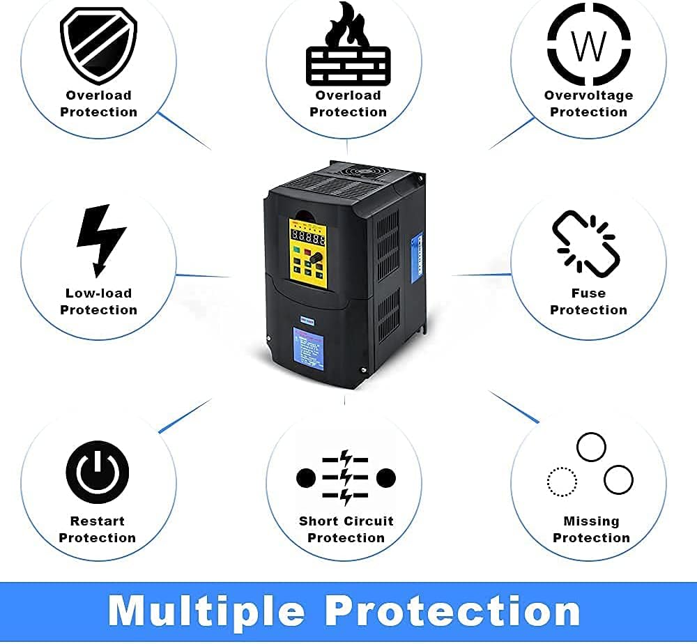
Figure 4.1.1: Simplified wiring diagram showing input power connection to the VFD and output to a 3-phase motor. A circuit breaker is shown for safety.

Figure 4.1.2: Detailed basic connection diagram for the HKS VFD, illustrating input (R, S, T) and output (U, V, W) terminals, control signal inputs (FWD/STOP, REV/STOP, RESET, etc.), and external potentiometer connections.
4.2. Power Connection Video Guide
Video 4.2.1: This video demonstrates how to connect power to the HKS A2 Series VFD. It shows the process of opening the terminal cover and connecting the input wires to the R and T terminals for single-phase 220V power, ensuring proper voltage difference. The video also highlights the importance of securing connections.
5. Operation
5.1. Control Panel Overview

Figure 5.1.1: Illustration of the HKS VFD control panel, detailing the function of each button (RUN/STOP, SET, JOG, UP/DOWN, Adjustment Knob) and indicators (ERROR, FWD, REV, ANALOG, SEGMENT, PANEL, Digital LCD).
5.2. Initial Parameter Setting Guide
To ensure optimal performance and compatibility with your motor, follow these steps for initial parameter setup. This guide focuses on common settings for 50Hz parameters.
- Set pn32 (Parameter management) = 6 (initialization for 50Hz parameters).
- Set pn02 (Initial start up frequency by panel or other external signal) = Load rating frequency.
- Set pn03 (Source of runtime frequency) = 2 (Panel button).
- Set pn04 (Source of runtime command) = 1 (Panel button control).
- Set pn10 (Maximum runtime frequency) = Load rating frequency.
- Set pn12 (Motor rating frequency) = Load rating frequency.
Note: For 60Hz parameters, adjust relevant frequency settings accordingly. Consult the full manual for detailed parameter descriptions (Chapters 5-7).
Video 5.2.1: This video demonstrates the initial parameter setting guide for the HKS A2 Series VFD, specifically for 50Hz parameters. It shows how to navigate the menu and adjust parameters like pn32, pn02, pn03, pn04, pn10, and pn12 using the control panel buttons.
5.3. Jog Function
The JOG function allows for momentary operation of the motor at a preset low frequency. Press the JOG button to activate. The panel will indicate the JOG status.
Video 5.3.1: This video demonstrates the JOG function of the HKS A2 Series VFD. It shows how to activate the JOG function and observe the panel indicators for forward (FWD) and reverse (REV) operation.
6. Maintenance
Regular maintenance ensures the longevity and reliable operation of your HKS VFD. Always disconnect power before performing any maintenance.
- Keep the VFD clean and free from dust and debris.
- Ensure adequate ventilation around the unit to prevent overheating.
- Periodically check all wiring connections for tightness and signs of wear or damage.
- Inspect the cooling fan for proper operation and clear any obstructions.
- Avoid exposing the VFD to excessive moisture or corrosive environments.

Figure 6.1.1: Image showing the cooling fan and ventilation design of the HKS VFD, highlighting the importance of maintaining clear airflow for optimal performance and lifespan.
7. Troubleshooting
This section provides basic troubleshooting steps for common issues. For complex problems, contact customer support.
| Problem | Possible Cause | Solution |
|---|---|---|
| VFD does not power on. | No input power, loose connections, internal fuse blown. | Check power supply, verify wiring, inspect fuses (qualified personnel only). |
| Motor does not run. | Incorrect parameter settings, motor wiring error, overload. | Review parameter settings (e.g., pn02, pn03, pn04), check motor connections, reduce load. |
| Overload error. | Motor overloaded, VFD undersized for application, acceleration time too short. | Reduce load, ensure VFD power rating is sufficient (at least 15% higher than motor for heavy loads), increase acceleration time (pn08). |
| Overvoltage/Undervoltage error. | Input voltage outside acceptable range. | Verify input voltage is within 180-250V AC. |
| High temperature error. | Insufficient cooling, blocked vents, high ambient temperature. | Ensure proper ventilation, clear obstructions, consider cooling solutions. |
7.1. Protection Features

Figure 7.1.1: Visual representation of the various protection features integrated into the HKS VFD, including overload, low-load, overvoltage, fuse, restart, short circuit, and missing protection.
8. Specifications
| Feature | Detail |
|---|---|
| Power | 7.5KW (10HP) |
| Input Voltage | AC 220V (180-250V) |
| Input Phase | 1-phase or 3-phase |
| Output Voltage | 220V |
| Output Phase | 3-phase |
| Input Current | 35A |
| Output Current | 50A |
| Input Frequency | 40-60HZ |
| Output Frequency | 0-400HZ |
| Product Dimensions | 5 x 5 x 5 inches |
| Item Weight | 6.45 pounds |
| Recommended Uses | Compressor, CNC router, Spindle motor, Grinder |
9. Warranty and Support
For warranty information or technical support, please refer to the product packaging or contact HKS customer service. It is recommended to have your product model number (7.5KW 10HP 220V) and purchase details available when contacting support.
If you have complex needs or encounter issues not covered in this manual, please contact customer service for accurate advice. Attaching pictures of the load equipment parameters (e.g., motor nameplate) can assist in faster resolution.


