
1. Introduction and Overview
This manual provides detailed instructions for the installation, operation, and maintenance of your MSI MPG X570S Edge MAX WiFi Gaming Motherboard. This motherboard is designed to support AMD Ryzen 5000 series, 5000 G-series, 4000 G-series, 3000 series, 3000 G-series, 2000 series, and 2000 G-series desktop processors, offering a robust platform for high-performance computing.
Key features include:
- Support for DDR4 Memory, up to 5300+(OC) MHz.
- Lightning Fast Game experience with PCIe 4.0, Lightning Gen 4 x4 M.2, and USB 3.2 Gen 2.
- Premium Thermal Solution: Aluminum cover, MOSFET thermal pads rated for 7W/mK, additional choke thermal pads, and 3x M.2 Shield Frozr for high performance and stable operation.
- 2.5G LAN with LAN Manager and Intel Wi-Fi 6E Solution for secure, stable, and fast network connections.
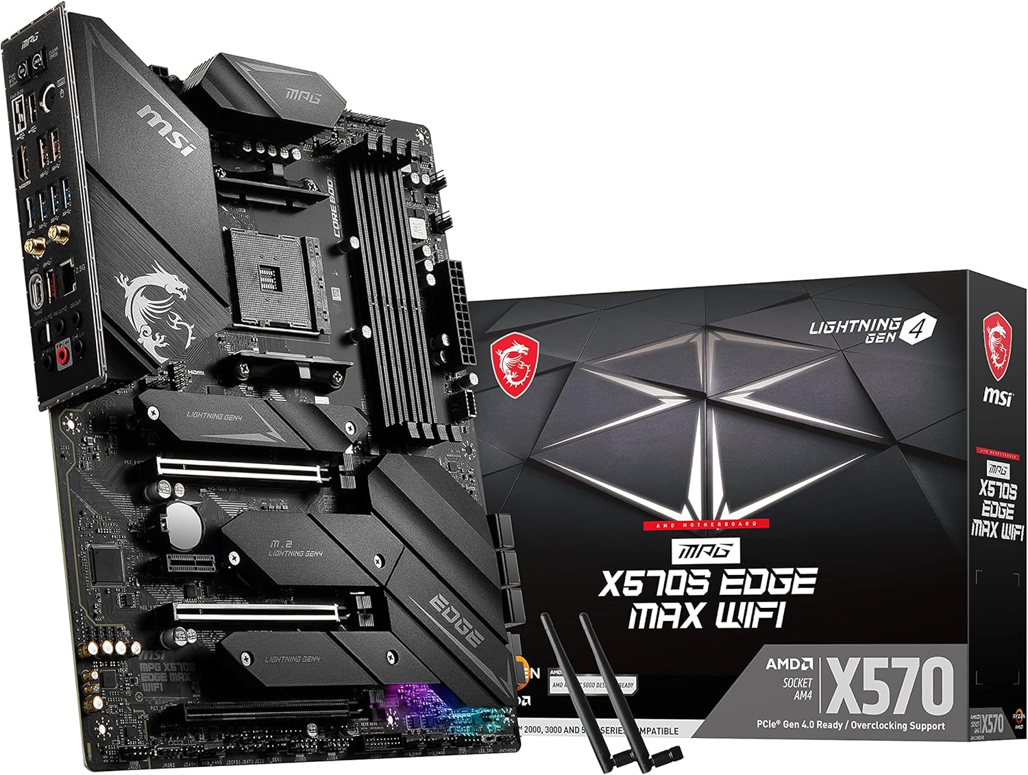
Figure 1.1: The MSI MPG X570S Edge MAX WiFi Motherboard alongside its retail packaging, showcasing the product's design and branding.

Figure 1.2: A banner image displaying the MSI MPG X570S Edge MAX WiFi Motherboard, highlighting its aesthetic design.
2. Setup and Installation
2.1 Package Contents
Before beginning installation, verify that all components are present in the package:
- MSI MPG X570S Edge MAX WiFi Motherboard
- Wi-Fi Antenna
- USB Drive (containing drivers)
- M.2 Screws
- SATA Cables (x2)
- Rainbow RGB LED Cable
- Thermistor Cable

Figure 2.1: The motherboard displayed with its various included accessories, such as the Wi-Fi antenna, USB drive, M.2 screws, SATA cables, RGB cable, and thermistor cable.
2.2 CPU Installation
The motherboard features an AM4 socket for AMD Ryzen processors. Carefully align your CPU with the socket, ensuring the golden triangle on the CPU matches the triangle on the socket. Lower the CPU gently into the socket, then secure it by closing the retention lever.

Figure 2.2: A detailed view of the AM4 CPU socket on the motherboard, indicating where the processor should be placed.
2.3 Memory (RAM) Installation
This motherboard supports DDR4 memory. Insert DDR4 memory modules into the DIMM slots, ensuring they are properly seated until the clips on both ends lock into place. Refer to the motherboard manual for specific dual-channel configurations.

Figure 2.3: An angled view of the motherboard highlighting the DDR4 memory slots and the 'DDR4 Boost' feature, along with 'Lightning Gen4' indicators for M.2 slots.

Figure 2.4: An illustration emphasizing the DDR4 Boost technology, capable of supporting memory speeds up to 5300+ MHz with A-XMP Profile 1.
2.4 Storage (M.2 SSD) Installation
The motherboard includes multiple M.2 slots with M.2 Shield Frozr heatsinks. To install an M.2 SSD, remove the Shield Frozr cover, insert the M.2 drive into the slot, and secure it with the provided screw. Reattach the Shield Frozr for optimal cooling.

Figure 2.5: A top-down view of the motherboard, clearly showing the layout of components including the CPU socket, RAM slots, and M.2 slots with their heatsinks.
2.5 PCIe Device Installation
Install your graphics card and other PCIe expansion cards into the appropriate PCIe slots. The motherboard features reinforced PCIe 4.0 x16 slots for heavy graphics cards.

Figure 2.6: An angled view of the motherboard highlighting the PCIe slots, including PCIe 4.0 x16 and PCIe 3.0 x1 slots, and indicating support for CrossFire technology.

Figure 2.7: A diagram illustrating the configuration of the PCIe slots, detailing the presence of PCIe 4.0 x16 and PCIe 3.0 x1 slots.
2.6 Power Connections
Connect the 24-pin ATX power connector and the 8-pin + 4-pin CPU power connectors from your power supply unit (PSU) to the corresponding ports on the motherboard.

Figure 2.8: A diagram highlighting the locations of the 4+8 pin CPU power connectors and other power input points on the motherboard.
2.7 Rear I/O Panel Connections
Connect your peripherals to the rear I/O panel. This includes USB devices, display cables (if using integrated graphics), Ethernet, and audio devices. Attach the Wi-Fi antennas for wireless connectivity.

Figure 2.9: A detailed view of the rear I/O panel, showing various ports including USB 2.0, HDMI 2.1, USB 3.2 Gen 1, Wi-Fi 6E antenna connectors, 2.5G LAN, USB 3.2 Gen 2 Type-C, and audio jacks, along with Flash BIOS and Clear CMOS buttons.

Figure 2.10: An illustration highlighting the integrated Wi-Fi 6E, 2.5G LAN, and Audio Boost features available on the motherboard's rear I/O panel.
3. Operating Instructions
3.1 Initial Boot and BIOS Setup
Upon first boot, access the BIOS/UEFI by pressing the designated key (usually DEL or F2) during startup. The BIOS interface is designed for easy navigation, allowing configuration of system settings, boot order, and enabling features like A-XMP for memory overclocking.
3.2 Driver Installation
After installing your operating system, install the necessary drivers from the included USB drive or download the latest versions from the MSI website. Ensure network drivers are installed to enable internet access for further updates.
3.3 Utilizing Advanced Features
- PCIe 4.0: Leverage the high bandwidth of PCIe 4.0 for compatible graphics cards and NVMe SSDs.
- Lightning Gen 4 M.2: Experience rapid storage performance with M.2 SSDs installed in the Lightning Gen 4 slots.
- Wi-Fi 6E & 2.5G LAN: Connect to high-speed wireless networks or utilize the 2.5 Gigabit Ethernet port for wired connections.

Figure 3.1: A bar chart comparing data transfer speeds of SATA, M.2, M.2 Shield Frozr, and Lightning Gen4 M.2, illustrating the superior performance of Lightning Gen4.
4. Maintenance
4.1 Thermal Management
The motherboard incorporates a premium thermal solution, including an aluminum cover, MOSFET thermal pads, and M.2 Shield Frozr heatsinks. Ensure proper airflow within your PC case to maintain optimal operating temperatures.

Figure 4.1: An angled view of the motherboard, highlighting its thermal design with icons representing 2oz Copper PCB, 6-layer PCB, Aluminum cover, and a thermal solution for high performance.

Figure 4.2: A diagram illustrating the various components of the motherboard's thermal solution, including the aluminum cover, MOSFET thermal pads, and M.2 Shield Frozr.

Figure 4.3: A graph demonstrating the effectiveness of the MSI M.2 Shield Frozr in maintaining stable M.2 SSD performance by preventing thermal throttling compared to a normal M.2 SSD.
4.2 Cleaning
Regularly clean dust from your PC components, including the motherboard, using compressed air. Ensure the system is powered off and unplugged before cleaning.
5. Troubleshooting
5.1 No Display/Boot Issues
- Verify all power connections (24-pin ATX, 8-pin + 4-pin CPU) are securely seated.
- Reseat RAM modules. Try booting with only one RAM stick.
- Ensure the graphics card is properly installed and connected to the monitor.
- Use the Clear CMOS Button on the rear I/O panel to reset BIOS settings to default if system instability occurs.
5.2 Network Connectivity Problems
- Ensure Ethernet cable is properly connected or Wi-Fi antennas are securely attached.
- Verify that network drivers are correctly installed. If not, download them from another device and transfer via USB.
5.3 BIOS Update
The motherboard features a Flash BIOS Button on the rear I/O panel, allowing you to update the BIOS without a CPU, memory, or graphics card installed. Refer to the MSI website for detailed instructions on using this feature.
6. Specifications
| Feature | Specification |
|---|---|
| Brand | MSI |
| Model Name | 911-7D53-004 |
| CPU Socket | Socket AM4 |
| Compatible Processors | AMD Ryzen 5000 Series, 5000 G-series, 4000 G-series, 3000 series, 3000 G-series, 2000 series, 2000 G-series |
| Chipset Type | AMD X570 |
| RAM Memory Technology | DDR4 |
| Memory Speed | Up to 5300+(OC) MHz |
| PCIe Slots | PCIe 4.0, PCIe 3.0 |
| M.2 Slots | 3x Lightning Gen 4 x4 M.2 |
| LAN | 2.5G LAN |
| Wireless Standard | Intel Wi-Fi 6E, Bluetooth |
| USB Ports | USB 3.2 Gen 2, USB 3.2 Gen 1, USB 2.0 |
| Product Dimensions | 30.48 x 24.38 x 6.35 cm (L x W x H) |
| Item Weight | 1 kg |
| Platform | Windows 10 |
7. Warranty and Support
For warranty information and technical support, please refer to the official MSI website or contact MSI customer service. Product registration may be required to activate your warranty. Keep your proof of purchase for warranty claims.
You can find additional resources and contact information on the MSI Official Website.


