
1. Introduction
This manual provides essential information for the safe and effective operation of your TOTAL TMT46004 DC/AC Clamp Meter. Please read this manual thoroughly before using the device and keep it for future reference. This clamp meter is designed for measuring DC/AC voltage, DC/AC current, resistance, capacitance, frequency, duty cycle, diode, and continuity.
2. Safety Information
Always adhere to basic safety precautions when using electrical testing equipment to reduce the risk of fire, electric shock, and personal injury. This device requires batteries for operation. It does not contain hazardous, toxic materials or waste subject to special transport, storage, or disposal regulations.
- Do not use the meter if it appears damaged or if the insulation on the test leads is compromised.
- Ensure the meter is set to the correct function and range before making measurements.
- Do not exceed the maximum input values for any range.
- Use caution when working with voltages above 60V DC or 30V AC RMS, as these pose a shock hazard.
- Always disconnect power to the circuit under test before measuring resistance, capacitance, or continuity.
- Replace batteries promptly when the low battery indicator appears to ensure accurate readings.
3. Product Overview
The TOTAL TMT46004 DC/AC Clamp Meter features a robust design for industrial and professional use. Key components include the current clamp, rotary switch, and LCD screen.
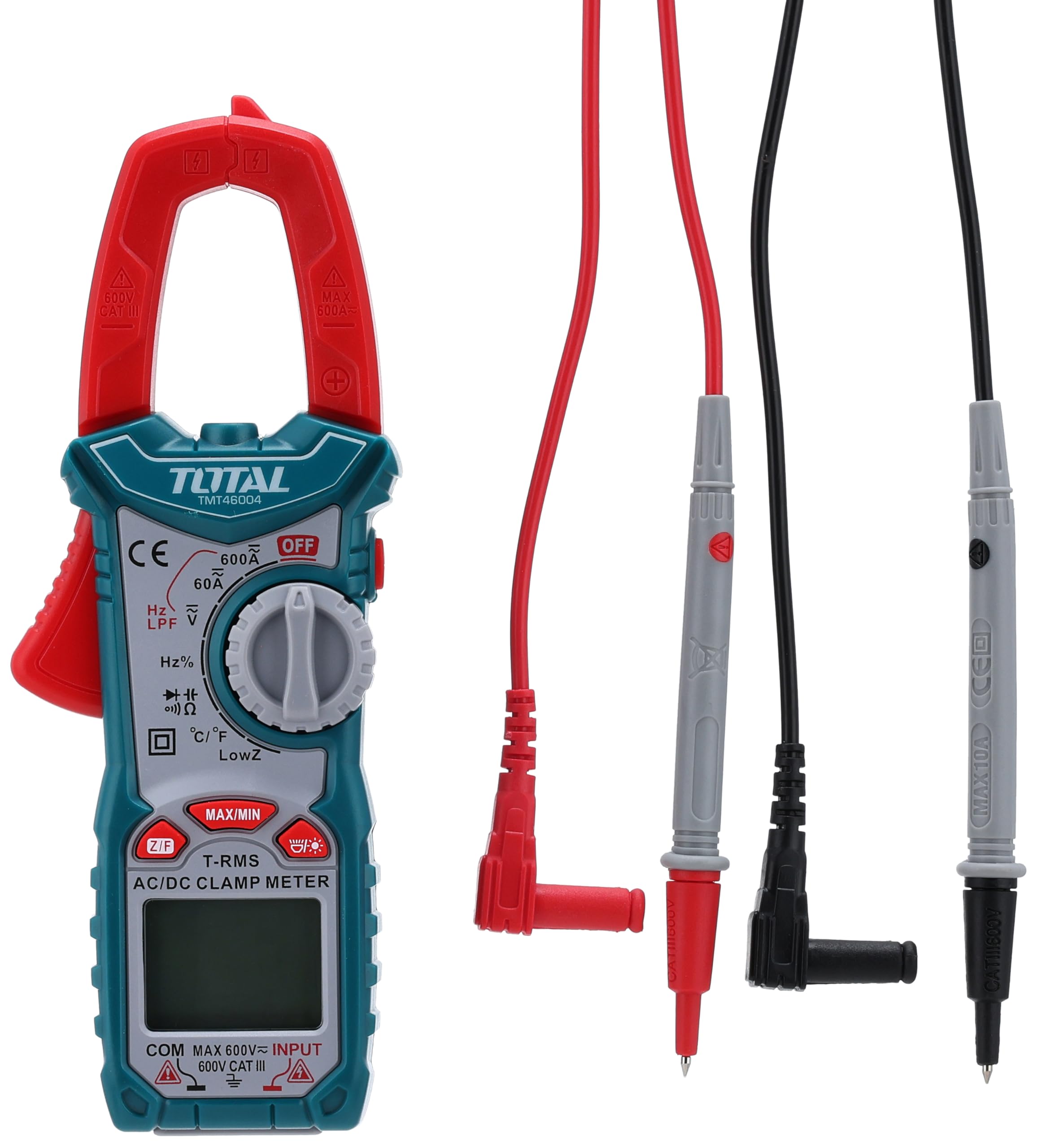
Figure 1: Packaging of the TOTAL TMT46004 Clamp Meter, showing the device and its main features.

Figure 2: Front view of the TOTAL TMT46004 Clamp Meter, highlighting the current clamp, rotary switch, and LCD display.
Components:
- Current Clamp: Used for non-contact measurement of AC/DC current.
- Rotary Switch: Selects the desired measurement function (Voltage, Current, Resistance, etc.).
- LCD Screen: Displays measurement readings and indicators.
- Input Jacks: For connecting test leads for voltage, resistance, capacitance, and other measurements.
- Function Buttons: Include MAX/MIN, Data Hold, NCV, Flashlight, and Zeroing functions.

Figure 3: Red and black test leads used with the clamp meter for various electrical measurements.
4. Setup
Battery Installation:
The TOTAL TMT46004 requires batteries for operation. To install or replace batteries:
- Ensure the meter is turned OFF.
- Locate the battery compartment cover on the back of the meter.
- Use a screwdriver to open the battery compartment.
- Insert new batteries, observing the correct polarity (+/-).
- Securely close the battery compartment cover.
Connecting Test Leads:
For voltage, resistance, capacitance, and continuity measurements, connect the test leads:
- Insert the black test lead into the 'COM' (common) input jack.
- Insert the red test lead into the 'VKΩHz' input jack for most measurements.
5. Operating Instructions
Before any measurement, ensure the meter is clean and the test leads are in good condition.
Measuring AC/DC Current (Clamp):
- Turn the rotary switch to the '600A' position for AC or DC current measurement.
- Press the trigger to open the current clamp.
- Enclose only one conductor of the circuit with the clamp jaws. Ensure the jaws are fully closed.
- Read the current value on the LCD screen.
Measuring AC/DC Voltage:
- Connect the test leads as described in the 'Connecting Test Leads' section.
- Turn the rotary switch to the 'V∼' for AC voltage or 'V—' for DC voltage.
- Touch the test probes to the circuit points where voltage is to be measured (in parallel with the load).
- Read the voltage value on the LCD screen.
Measuring Resistance (Ω):
- Ensure the circuit is de-energized before measuring resistance.
- Connect the test leads.
- Turn the rotary switch to the 'Ω' position.
- Touch the test probes across the component or circuit to be measured.
- Read the resistance value on the LCD screen.
Continuity Test:
- Ensure the circuit is de-energized.
- Connect the test leads.
- Turn the rotary switch to the 'KΩHz' position and select continuity if necessary.
- Touch the test probes across the circuit or component.
- A continuous beep indicates continuity (low resistance).
Non-Contact Voltage (NCV) Detection:
- Turn the rotary switch to the 'NCV' position.
- Move the top part of the meter near a live conductor.
- The meter will emit an audible beep and/or visual indication if AC voltage is detected.
6. Maintenance
Cleaning:
Wipe the meter with a damp cloth and mild detergent. Do not use abrasives or solvents. Keep the input terminals free of dirt and moisture.
Battery Replacement:
When the low battery indicator appears on the LCD, replace the batteries immediately to ensure accurate measurements. Refer to the 'Battery Installation' section for instructions.
Storage:
If the meter is not used for an extended period, remove the batteries to prevent leakage and damage. Store the meter in a cool, dry place, away from direct sunlight and extreme temperatures.
7. Troubleshooting
| Problem | Possible Cause | Solution |
|---|---|---|
| Meter does not turn on | Dead or incorrectly installed batteries | Check battery polarity or replace batteries. |
| No reading or 'OL' displayed | Incorrect range selected, open circuit, or measurement exceeds range. | Select a higher range, check circuit connections, or ensure the circuit is closed. |
| Inaccurate readings | Low battery, dirty test leads, or external interference. | Replace batteries, clean test leads, or move away from strong electromagnetic fields. |
| Continuity test not working | Circuit is not continuous (open) or incorrect function selected. | Verify circuit continuity, ensure the rotary switch is on the correct setting. |
8. Specifications
The following table details the technical specifications of the TOTAL TMT46004 DC/AC Clamp Meter.

Figure 4: Back of the TOTAL TMT46004 Clamp Meter packaging, showing detailed specifications.
| Specification | Range | Accuracy |
|---|---|---|
| DC Voltage | 600mV/6V/60V/600V | ±(0.5% + 5) |
| AC Voltage | 6V/60V/600V | ±(0.8% + 5) |
| DC Current | 60A/600A | ±(2.0% + 5) |
| AC Current | 60A/600A | ±(2.5% + 5) |
| Resistance | 600Ω/6kΩ/60kΩ/600kΩ/6MΩ/60MΩ | ±(1.0% + 5) |
| Capacitance | 10nF/100nF/1µF/10µF/100µF/1mF/10mF/100mF | ±(4.0% + 5) |
| Frequency | 10Hz/100Hz/1KHz/10KHz/100KHz/1000KHz | ±(1.0% + 3) |
| Duty Cycle | 1%~95% | ±(3.0% + 3) |
| Diode | Yes | |
| Continuity | Yes | |
| Data Hold | Yes | |
| NCV | Yes | |
| Flashlight | Yes | |
| RCA ZERO | Yes | |
| Low battery indication | Yes | |
| Auto power-off | Yes | |
| True RMS | Yes | |
| LPF | Yes | |
| MAX/MIN | Yes | |
| LowZ | Yes | |
| Temperature | °C/°F | ±(1.0% + 2) |
| Display | 6000 Counts LCD | |
| Material | High Carbon Steel | |
| Dimensions | 23 x 11.8 x 4.8 cm | |
| Weight | 438 grams |
9. Warranty and Support
For warranty information and technical support, please refer to the documentation provided with your purchase or contact TOTAL customer service. Keep your purchase receipt as proof of purchase.


