1. Introduction
This manual provides detailed instructions for the installation, operation, and maintenance of your DieseRC Wireless Remote Control Switch. This RF 433Mhz relay receiver system is designed for various applications, offering convenient remote control for devices such as motors, lights, and gate doors. Please read this manual thoroughly before use to ensure proper and safe operation.
2. Safety Information
Always observe the following safety precautions to prevent injury or damage to the device:
- Ensure the power supply voltage matches the product's specifications (DC 6V-30V).
- Disconnect power before performing any wiring or maintenance.
- Do not expose the device to moisture, extreme temperatures, or corrosive environments.
- Avoid short circuits during wiring. Incorrect wiring can damage the device or connected appliances.
- Keep the device out of reach of children.
- If the device malfunctions, discontinue use immediately and consult the troubleshooting section or contact support.
3. Product Overview
The DieseRC Wireless Remote Control Switch system consists of a relay receiver module and two remote control transmitters. The receiver features two independent relays, allowing for versatile control of two separate devices or functions.

Figure 3.1: Overview of the DieseRC Wireless Remote Control Switch system, showing the receiver module and two remote control transmitters.
Key Features:
- RF 433Mhz Wireless Control: Stable and reliable performance with high reception sensitivity.
- Long Range: Signal can pass through walls, floors, and doors, with a control distance of up to 30 meters.
- Secure Learning Code: Utilizes EV1527 learning code for enhanced system security.
- Dual Independent Relays: Two relays with Normally Open (NO), Common (COM), and Normally Closed (NC) terminals, allowing independent control.
- Multiple Operating Modes: Supports Momentary, Toggle, and Latched modes for flexible application.
- Wide Voltage Compatibility: Receiver operates on DC 6V to 30V.
- High Current Capacity: 10A relay with 15A high-power terminals.

Figure 3.2: Detailed view of the receiver board showing terminals (NO, COM, NC), antenna, indicator light, and learning button. The remote control features silicone buttons, an indicator light, chrome bezel, and a metal keychain.
4. Specifications
| Feature | Specification |
|---|---|
| Brand | DieseRC |
| Model Number | 2402 |
| Receiver Input Voltage | DC 6V ~ 30V |
| Output Voltage | 1V ~ 250V (Matches input voltage of connected device) |
| Max Current Rating | 10A (Relay), 15A (Terminal) |
| RF Frequency | 433Mhz |
| Control Distance | Up to 30 meters (open area) |
| Encoding Type | EV1527 Learning Code |
| Number of Relays | 2 (Independent) |
| Contact Type | Normally Open (NO), Common (COM), Normally Closed (NC) |
| Dimensions (Receiver Board) | Approx. 67mm x 49mm x 17mm (2.64in x 1.93in x 0.67in) |

Figure 4.1: Physical dimensions of the receiver board.
5. Setup and Pairing
The receiver supports pairing with up to 20 transmitters. Follow these steps to pair your remote controls with the receiver and set the desired operating mode.
Pairing Procedure:
The pairing process involves pressing the learning button on the receiver a specific number of times to select the operating mode, then pressing a button on the remote control to confirm pairing.
- Select Operating Mode: Press the learning button on the receiver board the corresponding number of times for your desired mode:
- Momentary Mode: Press the learning button 1 time.
- Toggle Mode: Press the learning button 2 times.
- Latched Mode: Press the learning button 3 times.
- Initiate Pairing: After pressing the learning button, the indicator light on the receiver will flash.
- Pair Transmitter: Within approximately 3 seconds, press the "A" button on your remote control. The indicator light on the receiver will flash again, indicating successful pairing.
- Confirm Pairing (Optional for some modes): For some modes, you may need to press the "B" button to complete the pairing for both relays or functions.

Figure 5.1: Visual guide for setting up and pairing the remote control with the receiver for different operating modes.
Resetting the Receiver:
To clear all paired transmitters from the receiver's memory, follow these steps:
- Press the learning button on the receiver board 8 times.
- The indicator light will flash rapidly, then turn off, indicating that all paired transmitters have been cleared.

Figure 5.2: Visual instruction for resetting the receiver module.
6. Operating Modes
The receiver offers three distinct operating modes to suit various control needs:
6.1. Momentary Mode (Jog Mode)
In Momentary Mode, the relay remains active only while the remote control button is pressed. Releasing the button deactivates the relay.
- Operation: Press and hold button "A" (or "B") on the remote. The corresponding relay will turn ON. Release the button, and the relay will turn OFF.
- Application: Ideal for applications requiring temporary activation, such as electric door locks, momentary light activation, or garage door openers where you hold the button until the door moves.
6.2. Toggle Mode (Self-Locking Mode)
In Toggle Mode, each press of a remote control button reverses the state of the corresponding relay (ON to OFF, or OFF to ON).
- Operation: Press button "A" (or "B") once. The corresponding relay will turn ON. Press the same button again, and the relay will turn OFF.
- Application: Suitable for controlling lights, fans, or other devices that need to be switched ON or OFF with a single button press.
6.3. Latched Mode (Interlock Mode)
In Latched Mode, pressing one button turns on its corresponding relay and simultaneously turns off any other active relays. This mode is typically used for controlling devices with two states, like opening and closing a gate.
- Operation: Press button "A". Relay 1 will turn ON, and Relay 2 will turn OFF (if it was ON). Press button "B". Relay 2 will turn ON, and Relay 1 will turn OFF (if it was ON).
- Application: Commonly used for controlling motors with forward/reverse functions, or gate/curtain openers where only one action (open/close) should be active at a time.
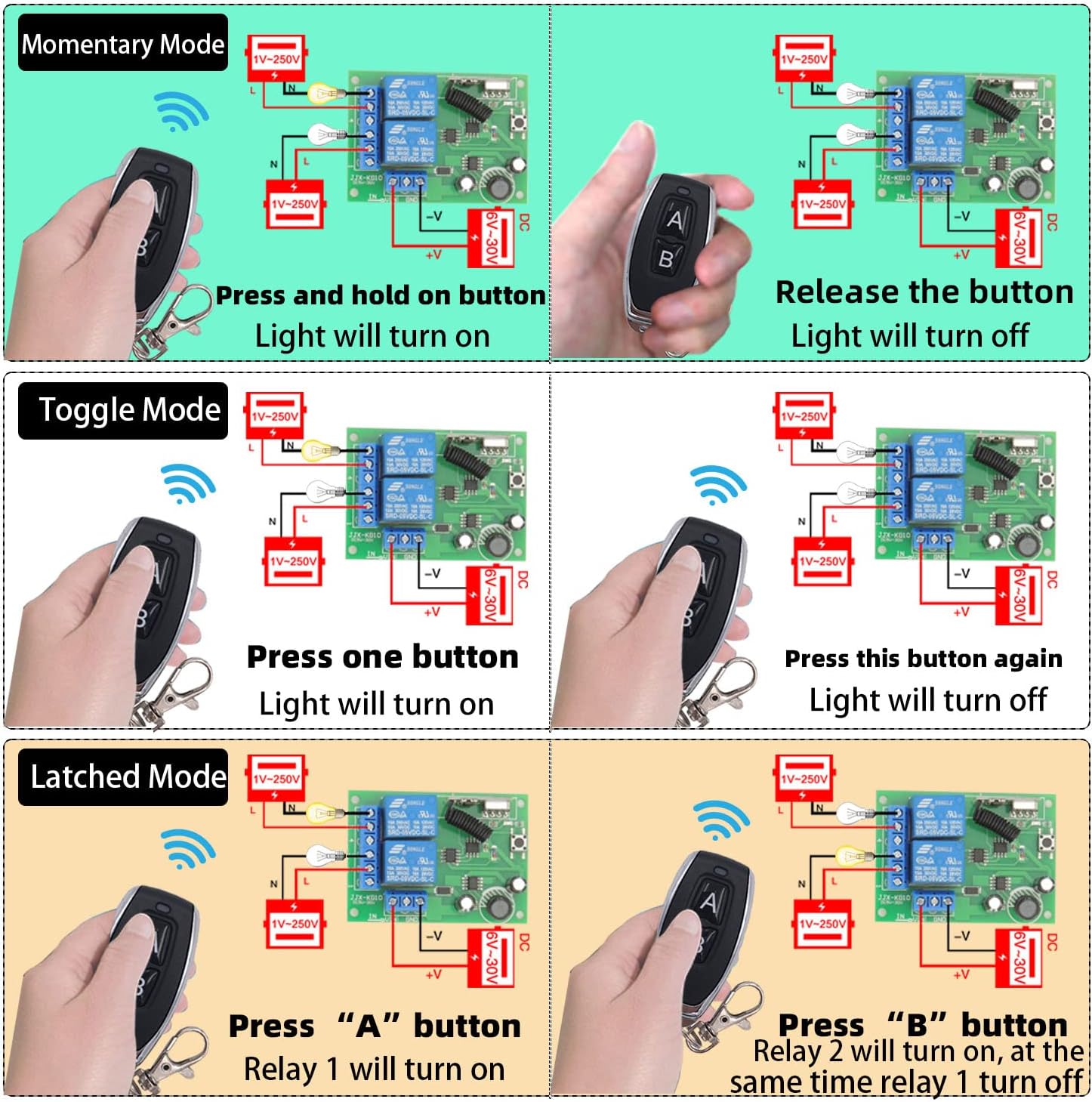
Figure 6.1: Illustration of the three operating modes and their corresponding relay behaviors.
7. Wiring Diagrams
Proper wiring is crucial for the safe and correct operation of the device. Refer to the diagrams below for common wiring configurations. Always ensure power is disconnected before making any connections.
7.1. DC Device Wiring (e.g., DC Lamp)
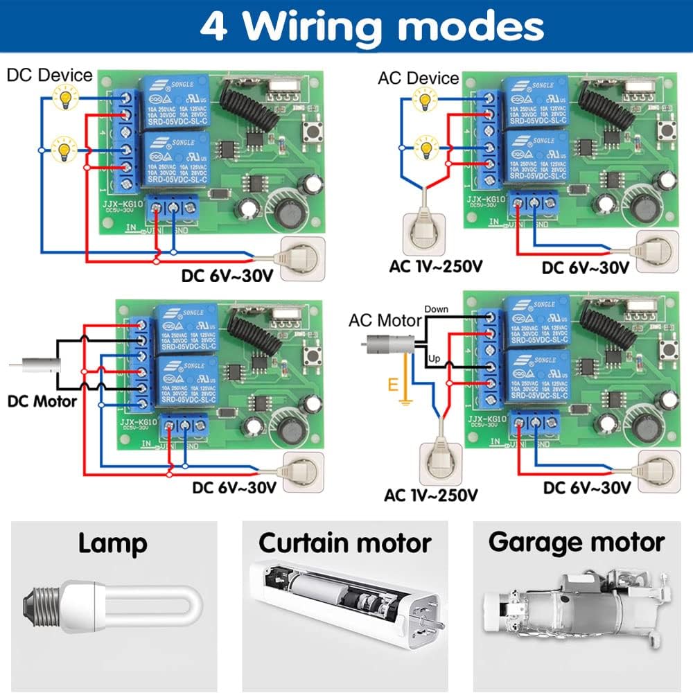
Figure 7.1: Wiring for a DC device (e.g., a DC lamp). Connect the DC power supply to the IN terminals (+V and -V) and the device to the NO/COM terminals of the relay.
7.2. AC Device Wiring (e.g., AC Lamp)
Figure 7.2: Wiring for an AC device (e.g., an AC lamp). Connect the AC power supply to the NO/COM terminals of the relay, and the receiver's power input (DC 6V-30V) separately.
7.3. DC Motor Wiring (e.g., Curtain Motor)
Figure 7.3: Wiring for a DC motor (e.g., a curtain motor). This typically uses two relays in Latched mode for forward/reverse control. Ensure correct polarity.
7.4. AC Motor Wiring (e.g., Garage Door Motor)

Figure 7.4: Wiring for an AC motor (e.g., a garage door motor). This setup also typically uses two relays in Latched mode for directional control. Ensure proper grounding and safety.
Note: The receiver's power input (DC 6V-30V) is separate from the power supplied to the controlled device (1V-250V). Always consult a qualified electrician if you are unsure about wiring connections, especially for AC applications.
8. Maintenance
To ensure the longevity and optimal performance of your DieseRC Wireless Remote Control Switch, follow these maintenance guidelines:
- Cleaning: Wipe the receiver and transmitters with a soft, dry cloth. Do not use abrasive cleaners or solvents.
- Battery Replacement (Transmitters): If the remote control's range decreases or the indicator light dims, replace the battery. Refer to the transmitter's casing for battery type (typically a small coin cell battery).
- Environmental Conditions: Store and operate the device in a dry environment, away from direct sunlight, extreme temperatures, and high humidity.
- Connection Check: Periodically inspect wiring connections to ensure they are secure and free from corrosion.
9. Troubleshooting
If you encounter issues with your DieseRC Wireless Remote Control Switch, refer to the following common problems and their solutions:
| Problem | Possible Cause | Solution |
|---|---|---|
| Receiver does not respond to remote. |
|
|
| Reduced control range. |
|
|
| Connected device does not turn ON/OFF. |
|
|
| Relay clicks but device doesn't activate. |
|
|
10. Warranty and Support
DieseRC is committed to providing high-quality products and customer satisfaction. While specific warranty details are not provided in this manual, DieseRC products are designed for durability and reliability.
If you encounter any issues that cannot be resolved using the troubleshooting guide, or if you require further assistance, please contact DieseRC customer support through the retailer where you purchased the product or visit the official DieseRC brand store for contact information.
For more information about DieseRC and their products, you can visit their brand store: DieseRC Official Store


