
1. Introduction
The EVTSCAN PEAKMETER MS5910 is a high-reliability, stable, and accurate digital resistance meter designed for electrical inspection and maintenance. This instrument combines RCD (Residual Current Device) and Loop testing functionalities into a compact, sturdy, and portable device. It is capable of measuring trip current, trip time, contact voltage, and loop resistance, and can store up to 100 sets of test results for later transfer to a PC via a USB 2.0 interface.
2. Safety Information
WARNING: To avoid electrical shock, remove test leads before opening the case or battery cover.
- Always read and understand this manual before operating the device.
- Ensure the device is powered off and disconnected from any circuits before performing maintenance or battery replacement.
- Do not use the device if it appears damaged or is operating abnormally.
- Adhere to all local and national safety regulations when performing electrical tests.
- The device is rated for CAT III 600V (2000m elevation) and CAT II 600V (3000m elevation). Do not exceed these ratings.
- Use only specified test leads and accessories.
3. Product Features
- Measures RCD trip current, trip time, contact voltage, and loop resistance.
- Stores up to 100 sets of test results.
- USB 2.0 interface for data transfer to PC.
- Backlight indication for improved visibility.
- Automatic power-off function to conserve battery life.
- Auto/manual ranging capabilities.
- Compact, sturdy, and portable design.
4. Package Contents
Verify that all items are present in the package:
- 1 x RCD/LOOP Tester MS5910
- 1 x Test Lead Set
- 3 x Crocodile Clips
- 1 x USB Cable
- 1 x Black Carrying Bag
- 1 x Instruction Manual (this document)
5. Device Overview
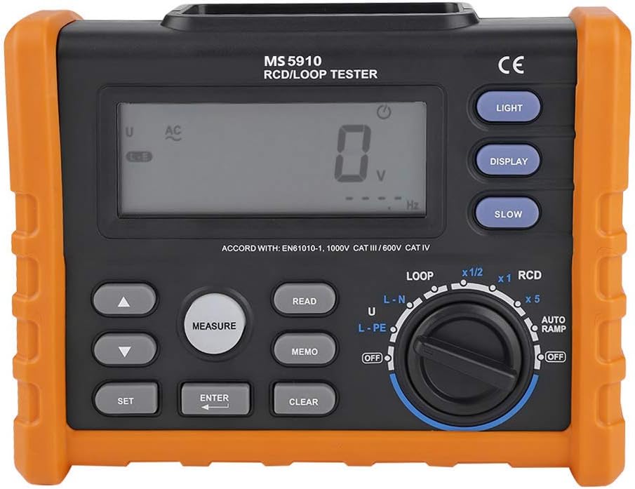
Figure 5.1: Front view of the EVTSCAN PEAKMETER MS5910 RCD Loop Tester, showing the display, function dial, and control buttons.

Figure 5.2: Bottom view of the MS5910, highlighting the USB interface and AC power input (AC IN 80V~440V).
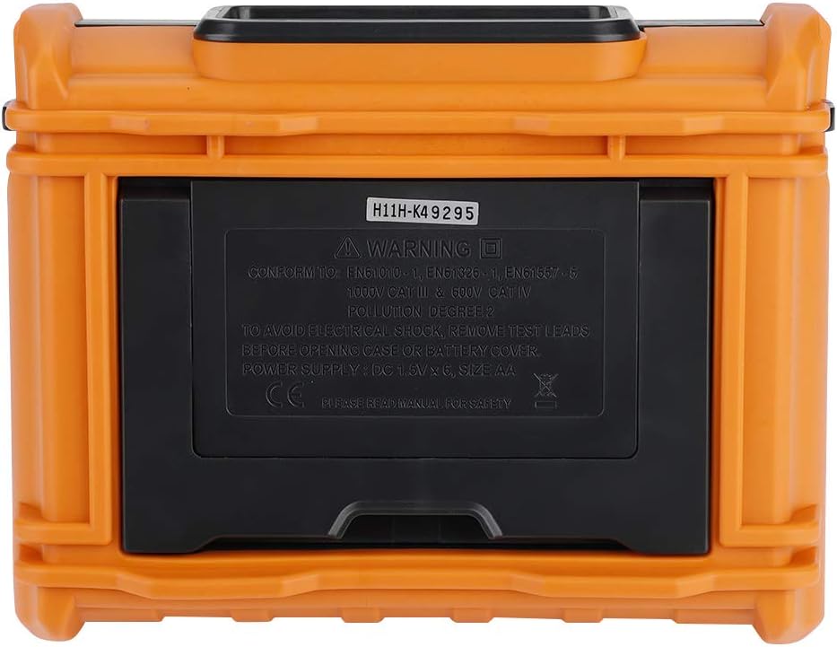
Figure 5.3: Rear view of the MS5910, showing the battery compartment cover and safety warnings.
6. Setup
6.1. Battery Installation
The MS5910 requires 6 x 1.5V AA batteries (not included). To install the batteries:
- Ensure the device is powered off and all test leads are disconnected.
- Locate the battery compartment on the rear of the device (refer to Figure 5.3).
- Use a suitable tool to open the battery compartment cover.
- Insert 6 AA batteries, observing the correct polarity (+/-) as indicated inside the compartment.
- Securely close the battery compartment cover.
Note: Replace batteries when the low battery indicator appears on the display.
6.2. Connecting Test Leads
Connect the provided test leads to the appropriate input terminals on the device. Ensure a secure connection for accurate measurements and safety.
7. Operating Instructions
7.1. Power On/Off
Press the POWER button to turn the device on or off. The device features an auto power-off function to save battery life if inactive for a period.
7.2. Display Backlight
Press the LIGHT button to toggle the display backlight on or off, improving visibility in low-light conditions.
7.3. Function Selection
Use the large rotary dial on the front panel to select the desired measurement function (e.g., LOOP, RCD). The dial has positions for different test current multipliers and RCD types.
7.4. RCD Testing (Residual Current Device)
The RCD test function measures the trip current, trip time, and contact voltage of Residual Current Devices. Follow these general steps:
- Connect the test leads to the circuit under test and the MS5910.
- Turn the rotary dial to the RCD section.
- Select the desired RCD test current multiplier (e.g., x1/2, x1, x5) and RCD type (Standard/Selective) using the dial and possibly the SET buttons.
- Press the MEASURE button to initiate the test.
- Observe the results on the display.
Refer to the RCD tests current selection table in the Specifications section for detailed current levels.
7.5. Loop Resistance Testing
The Loop test function measures the loop resistance of electrical circuits. Follow these general steps:
- Connect the test leads to the circuit under test and the MS5910.
- Turn the rotary dial to the LOOP section.
- Select the appropriate connection type (L-N, U, L-PE) using the dial.
- Press the MEASURE button to initiate the test.
- Observe the loop resistance value on the display.
7.6. Data Storage and Transfer
The MS5910 can store up to 100 sets of test results. Use the MEMO button to save current readings. To transfer data to a PC:
- Connect the MS5910 to a computer using the provided USB cable (refer to Figure 5.2).
- Install any necessary drivers or software (if applicable, refer to manufacturer's website for downloads).
- Follow the software instructions to download and analyze the stored test data.
8. Maintenance
- Cleaning: Wipe the device with a dry, soft cloth. Do not use abrasive cleaners or solvents.
- Battery Replacement: Replace batteries as described in Section 6.1 when the low battery indicator appears. Remove batteries if the device will not be used for an extended period.
- Storage: Store the device in a cool, dry place, away from direct sunlight and extreme temperatures. Use the provided carrying bag for protection.
- Calibration: For continued accuracy, periodic calibration by qualified personnel is recommended.
9. Troubleshooting
| Problem | Possible Cause | Solution |
|---|---|---|
| Device does not power on. | Dead or incorrectly installed batteries. | Check battery polarity and replace batteries if necessary. |
| Inaccurate readings. | Loose test lead connections; device out of calibration; incorrect function selected. | Ensure test leads are securely connected. Verify correct function selection. Consider professional calibration. |
| Display shows "OL" or error message. | Measurement range exceeded; open circuit. | Check the circuit for continuity. Ensure the measurement is within the device's specified range. |
| Data transfer fails. | USB cable not connected properly; missing drivers. | Reconnect USB cable. Install necessary drivers or software from the manufacturer. |
10. Specifications
| Parameter | Range | Accuracy | Resolution |
|---|---|---|---|
| Tripping time (x1 ΔIN300) | Slow 500ms | ±3ms | 0.1ms |
| Tripping time (x5 ΔIN40ms) | Slow 150ms | ±3ms | 0.1ms |
| Tripping current | (0.2~1.1)ΔIN | ±0.1 ΔIN | 0.05 ΔIN |
| Contact voltage | 0~99.9V | ±(10%+0.2V) | 0.01, 0.1V |
| AC voltage (UI-N, UL-L, UL-E) | 0~440V | ±(3%+3V) | 1V |
| Frequency | DC, 45~65Hz | ±1Hz | 1Hz |
| Loop resistance (RL) | 0~19.9Ω | ±(10%+0.2V) | 0.01V |
| Loop resistance (RL) | 10.0~99.9Ω | ±(10%+0.2V) | 0.1V |
| RL Test current | 0.5IΔN | ±(10%+10d) | 0.05IΔN |
| Test current multiplier | x0.5, x1, x5 | ||
| Current level (ΔIN) | 10mA, 30mA, 100mA, 300mA, 500mA | ||
| Trigger phase Angle | 0° or 180° |
General Specifications:
- Power Supply: 6 x 1.5V AA batteries (not included)
- Storage Elevation: 12,000m
- Usage Elevation: 2,000m CAT III 600V; 3,000m CAT II 600V
- Dimensions: 195 x 155 x 80mm (7.68 x 6.1 x 3.15 inches)
- Weight: Approximately 2194g (4.82 pounds)
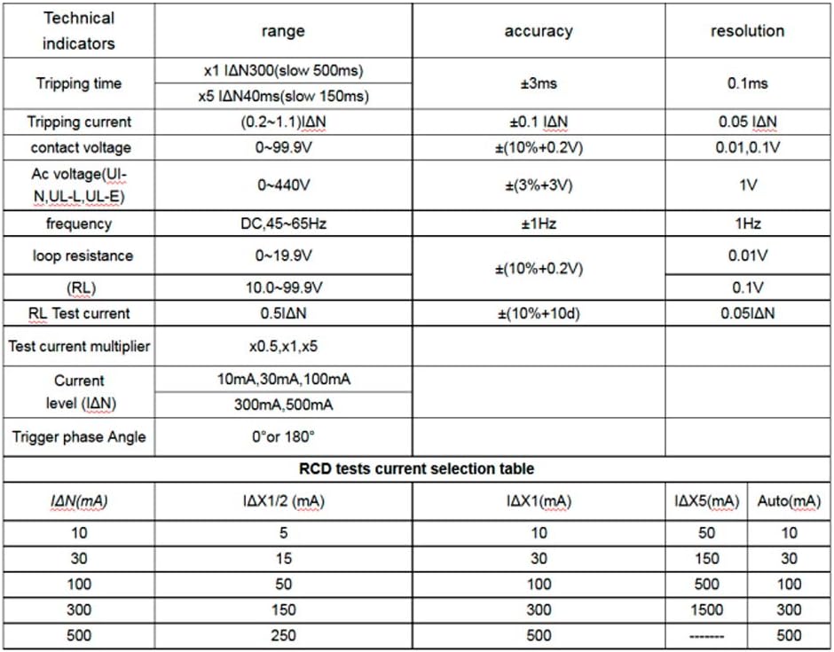
Figure 10.1: Detailed technical indicators and RCD test current selection table.
11. Warranty and Support
This product is manufactured by EVTSCAN. For warranty information, technical support, or service inquiries, please refer to the documentation included with your purchase or visit the official EVTSCAN website. Keep your purchase receipt as proof of purchase for warranty claims.
For further assistance, you may contact the seller directly through the platform where the purchase was made.