1. Product Overview
This manual provides essential information for the installation, operation, and maintenance of the Allen-Bradley Barrel Ceramic Heater Band, Model 203613. This industrial component is designed to provide efficient and uniform heating for various applications, typically involving barrels or cylindrical containers.
The heater band operates at 2300W and 460V, making it suitable for high-power industrial heating requirements. It features a ceramic construction for durability and effective heat transfer.
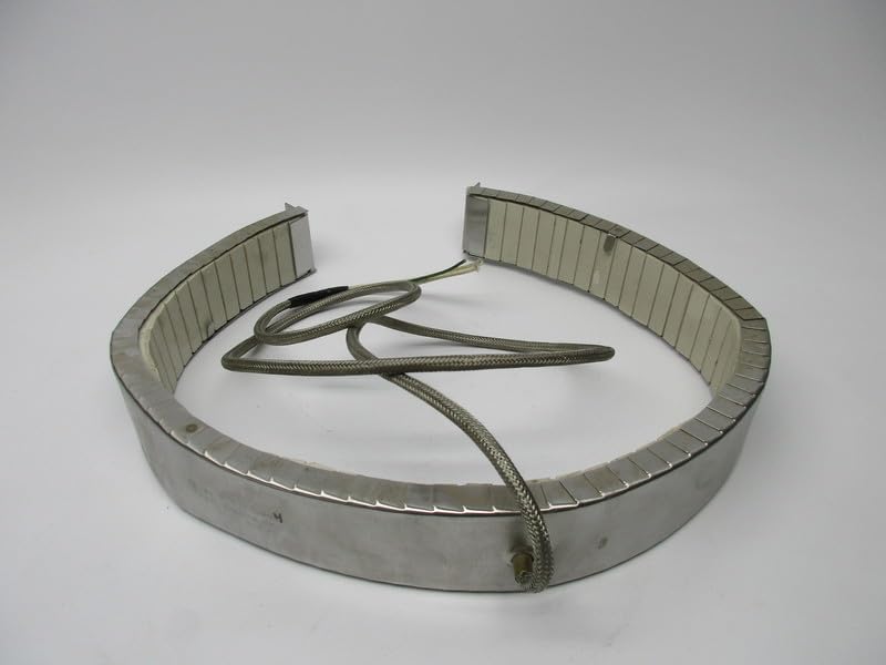
Figure 1: Allen-Bradley Barrel Ceramic Heater Band, Model 203613. This image shows the full heater band, which is semi-circular and made of metal with ceramic segments visible on the inside. A braided wire extends from one end.
2. Safety Information
Always adhere to local electrical codes and safety regulations when installing or operating this device. Failure to do so may result in property damage, serious injury, or death.
- Electrical Hazard: Ensure power is disconnected before installation, maintenance, or troubleshooting.
- Burn Hazard: The heater band operates at high temperatures. Allow sufficient cooling time before handling.
- Qualified Personnel: Installation and servicing should only be performed by qualified and authorized personnel.
- Proper Grounding: Ensure the heater band is properly grounded according to electrical standards.
- Environmental Conditions: Do not expose the heater band to moisture or corrosive environments unless specifically rated for such conditions.
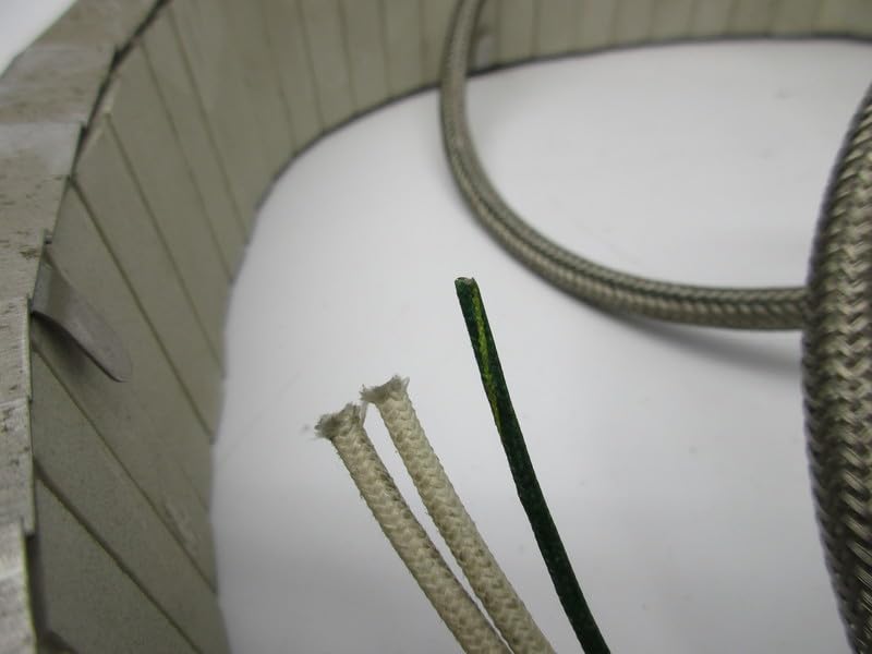
Figure 2: Close-up view of the electrical connection wires of the heater band. Note the exposed wire ends, emphasizing the need for proper electrical termination and safety precautions.
3. Setup and Installation
- Inspect the Unit: Before installation, visually inspect the heater band for any signs of damage during shipping. Do not install damaged units.
- Prepare the Surface: Ensure the barrel or cylindrical surface where the heater band will be installed is clean, dry, and free of any obstructions.
- Positioning: Carefully position the heater band around the barrel, ensuring a snug fit. The band should make full contact with the surface for optimal heat transfer.
- Secure the Band: Use the integrated clamping mechanisms or mounting points to securely fasten the heater band. Ensure even pressure around the circumference.
- Electrical Connection:
- Verify that the power supply matches the heater band's voltage (460V) and wattage (2300W) requirements.
- Connect the heater band's leads to the appropriate power source terminals. Ensure all connections are tight and insulated.
- Implement proper grounding as per local electrical codes.
- Initial Power-Up: After installation, perform a low-power test if possible, or carefully monitor the unit during its first operation to ensure proper function and no abnormal conditions.
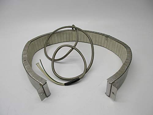
Figure 3: The heater band showing its full semi-circular form and the mounting tabs at each end. These tabs are used to secure the band around a cylindrical object, ensuring proper contact for heating.
4. Operating Instructions
The Barrel Ceramic Heater Band is designed for continuous operation within its specified parameters. Operation typically involves connecting it to a temperature control system (not included) to regulate the heating process.
- Temperature Control: Connect the heater band to a suitable temperature controller. Set the desired temperature according to your application requirements.
- Power On: Activate the power supply to the heater band. The temperature controller will then manage the heating cycle.
- Monitoring: Periodically monitor the temperature and the heater band's performance to ensure it is operating within normal limits.
- Power Off: To cease operation, disconnect the power supply to the heater band. Allow the unit to cool down naturally.
5. Maintenance
Regular maintenance ensures the longevity and efficient operation of your heater band. Always disconnect power before performing any maintenance.
- Cleaning: Keep the exterior of the heater band clean and free from dust, debris, or chemical residues. Use a dry cloth for cleaning. Do not use abrasive cleaners or solvents.
- Connection Check: Periodically inspect electrical connections for tightness and signs of corrosion or wear. Re-tighten connections as necessary.
- Physical Inspection: Check the heater band for any physical damage, cracks in the ceramic, or deformation of the metal casing. Replace the unit if significant damage is observed.
- Mounting Security: Ensure the mounting hardware remains secure and the band maintains firm contact with the heated surface.
6. Troubleshooting
| Problem | Possible Cause | Solution |
|---|---|---|
| Heater not heating | No power supply; Faulty wiring; Open circuit in heater; Temperature controller issue. | Check power source and circuit breaker; Inspect wiring for breaks or loose connections; Test heater continuity; Verify temperature controller settings and function. |
| Uneven heating | Poor contact with barrel surface; Damaged ceramic elements. | Ensure heater band is securely clamped and making full contact; Inspect ceramic elements for cracks or damage. |
| Overheating | Faulty temperature controller; Incorrect temperature setting. | Check and recalibrate temperature controller; Verify temperature settings. |
If troubleshooting steps do not resolve the issue, contact qualified service personnel or the manufacturer for assistance.
7. Specifications
| Attribute | Value |
|---|---|
| Model Number | 203613 |
| Type | Barrel Ceramic Heater Band |
| Power Rating | 2300W |
| Voltage | 460V |
| Manufacturer | INDUSTRIAL MRO |
| ASIN | B097HR9PMQ |
| Condition Notes | NSFS – New Surplus Factory Sealed (OEM), NSMP – New Surplus Manufacturer Package (OEM), NSNP – New Surplus No Manufacturer Package (OEM), NUPI - New Unused Previously Installed (OEM), REMAN – Remanufactured Like New (OEM) |
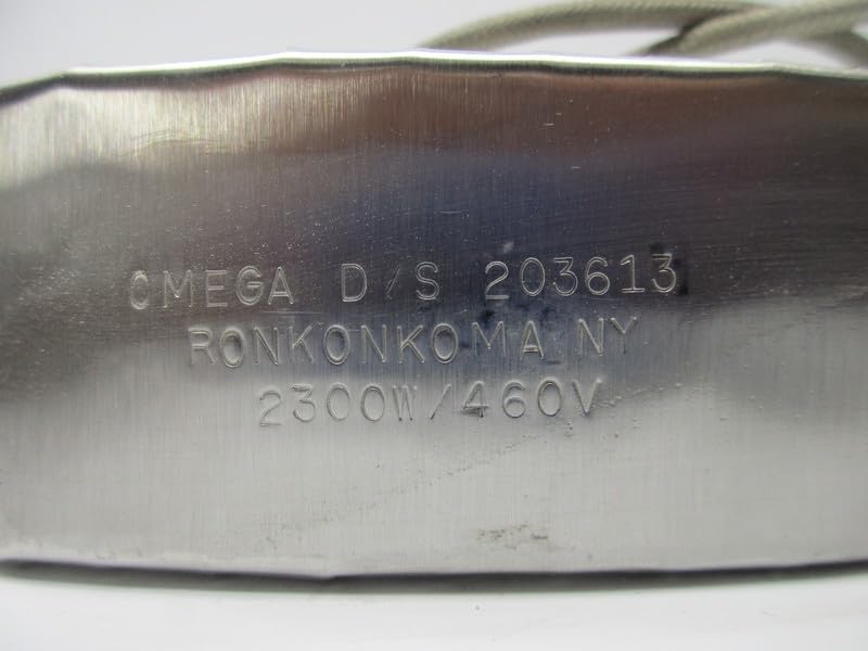
Figure 4: A close-up image showing engraved text on the metal casing of the heater band, indicating "OMEGA D/S 203613 RONKONKOMA NY 2300W/460V". This confirms the model number and electrical specifications.
8. Warranty and Support
This product is often sold as a surplus item. Therefore, specific warranty terms may vary depending on the seller and the condition of the item (e.g., New Surplus, Remanufactured). Please refer to your purchase agreement or contact your supplier for detailed warranty information.
For technical support or inquiries regarding this Allen-Bradley component, it is recommended to contact the original equipment manufacturer (OEM) or a certified industrial MRO supplier. The manufacturer listed is INDUSTRIAL MRO.
Legal Disclaimer: Surplus Item - Package Condition/Type May Vary.


