
seeed studio LoRa-E5
Seeed Studio LoRa-E5 Development Kit User Manual
Comprehensive guide for setting up, operating, and maintaining your LoRa-E5 Development Kit.
1. Introduction
The Seeed Studio LoRa-E5 Development Kit is an advanced toolset designed for rapid prototyping and testing of LoRaWAN applications. It integrates the powerful LoRa-E5 STM32WLE5JC module, which combines a LoRa RF and MCU chip into a single, compact unit. This kit is ideal for developers and engineers working on ultra-low power, long-range wireless communication projects.
The kit supports global LoRaWAN and LoRa frequency plans, offering high performance and ultra-low power consumption, making it suitable for a wide range of IoT applications requiring extended transmission distances.
2. Package Contents
Upon opening your Seeed Studio LoRa-E5 Development Kit, please verify that all the following components are included:
- 1 x LoRa-E5 Dev Board
- 1 x Antenna (EU868/US915)
- 1 x USB Type-C Cable
- 1 x 2*AA 3V Battery Holder

Figure 2.1: All components included in the LoRa-E5 Development Kit. This image displays the LoRa-E5 Dev Board, a black antenna, a black USB Type-C cable, and a black 2*AA 3V battery holder with red and black wires.
3. Key Features
- Ultra-low power consumption and high performance: The LoRa-E5 module's sleep current is as low as 2.1uA (WOR mode), ensuring efficient operation.
- Easy testing and rapid prototyping: User-friendly design allows for quick setup and development.
- Full GPIOs led out to rich interfaces: Includes RS-485, Grove connectors (IIC, UART), JST2.0, SMA-K, and IPEX for versatile connectivity.
- Global LoRaWAN and LoRa frequency plan supported: Compatible with EU868, US915, AU915, AS923, KR920, and IN865 frequencies.
- Long-distance transmission range: Capable of transmitting up to 10km in open areas.
- FCC and CE certified: Ensures compliance with international standards.
- Powered by ARM Cortex-M4 core and Semtech SX126X LoRa chip.
4. Technical Specifications
| Parameter | Value |
|---|---|
| Model Name | LoRa-E5 |
| Board Dimensions | 85.6 x 54 mm |
| Input Voltage (Battery) | 3-5V |
| Input Voltage (USB Type C) | 5V |
| Output Voltage | EN 3V3 / 5V |
| Power Output | Up to +20.8dBm at 3.3V |
| Supported Frequencies | EU868 / US915 / AU915 / AS923 / KR920 / IN865 |
| Protocol | LoRaWAN |
| Sensitivity | -116.5dBm ~ -136dBm |
| Interfaces | USB Type C, JST2.0, Grove*3 (IIC*2/UART*1), RS485, SMA-K, IPEX |
| Modulation | LoRa, (G)FSK, (G)MSK, BPSK |
| Operating Temperature | -40℃ ~ 85℃ |
| Sleep Current (LoRa-E5 module) | As low as 2.1uA (WOR mode) |
| Memory Storage Capacity | 256 KB |
| RAM Memory Installed Size | 64 KB |
5. Hardware Overview
The LoRa-E5 Dev Board is the central component of the kit, designed to expose the full functionality of the LoRa-E5 module. It features a compact layout with various connectors and pin headers for easy integration with other sensors and modules.

Figure 5.1: Top view of the LoRa-E5 Dev Board, showing various headers, connectors, and the LoRa-E5 module.
5.1 Pinout Diagram
Understanding the pinout is crucial for proper connection and programming. The board provides access to all 28 pins of the LoRa-E5 module.

Figure 5.2: LoRa-E5 Dev Board Pinout, illustrating the assignment of various pins including Power, GND, RST, Analog, Digital, SWD, IIC, SPI, UART, LPUART, and USART.
5.2 Hardware Components
The board integrates several key components and connectors to facilitate development:

Figure 5.3: Hardware Specification diagram, labeling components such as SPI-Flash Bonding Pad, RESET Button, Grove Connector, RS-485, IPEX MHF Antenna Connector, SMA Antenna Connector, LoRa-E5 (STM32WLE5JC) module, RS-485 Connector, JST2.0 Battery Connector, LED Indicators, Temperature Sensor, User Button, Boot Button, and various pin headers.
- LoRa-E5 (STM32WLE5JC): The core module for LoRa communication.
- USB Type-C Port: For power supply and data communication.
- JST2.0 Battery Connector (3-5V): Alternative power input for portable applications.
- SMA-K Antenna Connector: For connecting the external LoRa antenna.
- IPEX MHF Antenna Connector: An alternative antenna connection point.
- Grove Connectors: Three Grove connectors (two IIC, one UART) for plug-and-play connectivity with Seeed Studio's extensive range of Grove sensors and actuators.
- RS-485 Terminal: For industrial communication.
- Reset and Boot Buttons: For controlling the board's state.
- LED Indicators: For power, TX, and RX status.
6. Setup Guide
6.1 Connecting the Antenna
- Locate the SMA-K Antenna Connector on the LoRa-E5 Dev Board (refer to Figure 5.3).
- Carefully screw the provided antenna onto the SMA-K connector until it is finger-tight. Do not overtighten.
- Ensure the antenna is positioned vertically for optimal signal reception and transmission.
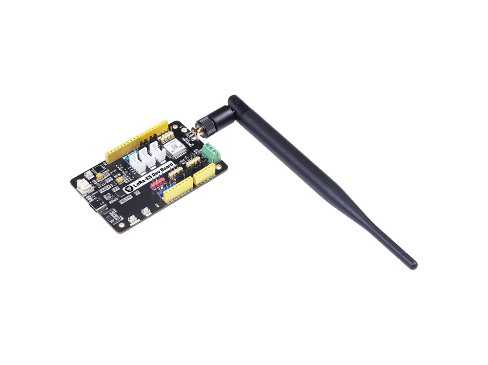
Figure 6.1: The LoRa-E5 Dev Board with the black external antenna securely attached to the SMA connector.
6.2 Powering the Board
The LoRa-E5 Dev Board can be powered via two methods:
- USB Type-C: Connect the provided USB Type-C cable to the USB port on the board and to a 5V power source (e.g., computer USB port, USB wall adapter). This is the primary method for development and programming.
- Battery Holder: For portable applications or temporary use, connect the 2*AA 3V Battery Holder to the JST2.0 Battery Connector. Ensure batteries are correctly inserted according to polarity markings.
Once powered, the power LED indicator on the board should illuminate.
7. Operating Instructions
The LoRa-E5 Dev Board is designed for flexible operation, supporting various development environments and communication protocols. Initial setup often involves flashing firmware or using AT commands.
7.1 Initializing the Board
For initial communication and configuration, the LoRa-E5 module typically responds to AT commands via a serial terminal. Connect the board to your computer via the USB Type-C cable. Use a serial terminal program (e.g., PuTTY, Tera Term, Arduino Serial Monitor) to establish a serial connection at the appropriate baud rate (commonly 9600 or 115200 bps).
Refer to the official Seeed Studio documentation and examples for specific AT command sets and firmware flashing procedures. Note that flashing custom firmware may overwrite the default AT command firmware.
7.2 Interfacing with Peripherals
The board offers multiple interfaces for connecting external sensors and modules:
- Grove Connectors: Utilize the dedicated Grove ports for plug-and-play connectivity with Seeed Studio's extensive range of Grove sensors and actuators.
- RS-485 Terminal: Connect RS-485 compatible devices for robust industrial communication.
- Pin Headers: Use the male and female pin headers to connect custom circuits or standard breadboard components, accessing GPIOs, I2C, SPI, and UART lines.
Always ensure correct voltage levels and pin assignments when connecting external components to prevent damage to the board or peripherals.
8. Maintenance
To ensure the longevity and optimal performance of your LoRa-E5 Development Kit, follow these maintenance guidelines:
- Storage: Store the kit in a dry, cool environment, away from direct sunlight and extreme temperatures. Use anti-static bags if available.
- Cleaning: Gently clean the board with a soft, dry brush or compressed air to remove dust. Avoid using liquids or abrasive cleaners.
- Handling: Handle the board by its edges to avoid touching sensitive electronic components. Always discharge static electricity before handling.
- Firmware Updates: Periodically check the Seeed Studio official website for firmware updates to ensure the best performance and access to new features.
9. Troubleshooting
This section addresses common issues you might encounter with your LoRa-E5 Development Kit.
| Problem | Possible Solution |
|---|---|
| Board does not power on. |
|
| Cannot establish serial communication. |
|
| LoRa communication issues. |
|
| Firmware flashing fails. |
|
If you encounter issues not listed here, or if the suggested solutions do not resolve your problem, please refer to the official Seeed Studio documentation or contact their technical support.
10. Warranty and Support
Seeed Studio products are designed and manufactured to high-quality standards. For detailed information regarding the warranty period and terms for your LoRa-E5 Development Kit, please refer to the warranty policy available on the official Seeed Studio website.
For technical assistance, documentation, and community support, please visit the official Seeed Studio website:
The website provides extensive resources, including tutorials, forums, and contact information for customer service.
Related documentsLoRa-E5


Ask a question about this manual
Ask about setup, troubleshooting, compatibility, parts, safety, or missing instructions. Manuals+ will review the question and use this page’s manual context to help answer it.