
1. Introduction
This manual provides detailed instructions for the proper use and maintenance of your SAMCOM 5Watt Long Range Two Way Radio, Model FPCN30A. This device is designed for reliable communication over various distances, featuring a 5-watt power output, 20 channels, and a durable design. Please read this manual thoroughly before operating the radio to ensure optimal performance and safety.

Image 1.1: SAMCOM FPCN30A Two-Way Radios with Speaker Microphones.
This image displays two SAMCOM FPCN30A two-way radios, each placed in its respective charging dock and connected to a speaker microphone. The radios are black with an LCD screen displaying channel information. This setup represents the complete product package.
2. Package Contents
Verify that all items listed below are included in your package:
- Two-Way Radio x 2
- Speaker Mic x 2
- Long Antenna (6.7 inches) x 2
- K-Type Earpiece x 2
- Charging dock x 2
- Charger x 2
- Back Clip x 2
- Working Manual x 2

Image 2.1: Included Package Contents.
This image displays all components typically found in the SAMCOM FPCN30A package. It shows two two-way radios, two speaker microphones, two K-type earpieces, two charging bases, and two power adapters (chargers). This visual confirms the items you should receive.
3. Product Overview
Familiarize yourself with the various parts of your SAMCOM FPCN30A radio:

Image 3.1: Labeled Components of the FPCN30A Radio.
This diagram provides a detailed view of the SAMCOM FPCN30A two-way radio, highlighting its key components. Labels include Antenna, Power/Volume Switch, Channel Selection Knob, Status Indicator, Speaker, Earpiece Cap, LCD Display, Keys (Menu, Group/OK, Exit/A), Charger contacts, PTT Transmitting Microphone, Monitor Button, Scan Button, Battery, Battery Release Button, Back Splint, and Belt Screw. Understanding these parts is crucial for operation.
- Antenna: For transmitting and receiving signals.
- Power/Volume Switch: Rotates to turn the radio on/off and adjust volume.
- Channel Selection Knob: Rotates to select desired communication channels.
- Status Indicator: LED light indicating radio status (e.g., transmitting, receiving, charging).
- Speaker: Outputs received audio.
- Earpiece Cap: Protects the earpiece/accessory port.
- LCD Display: Shows channel, battery status, and other settings.
- Keys (MENU, GROUP/OK, EXIT/A): For navigating menus and activating functions.
- PTT (Push-to-Talk) Button: Press and hold to transmit your voice.
- Monitor Button: Used to listen for weak signals on the current channel.
- Scan Button: Initiates channel scanning.
- Battery: Rechargeable Lithium Polymer battery.
- Speaker/Mic Port: Connects external speaker microphones or earpieces.

Image 3.2: Speaker/Mic Port Detail.
This close-up image shows the speaker and microphone ports on the side of the radio, designed for connecting external audio accessories like the included speaker microphone or earpiece. The ports are protected by a rubber cap when not in use.
4. Setup
4.1. Battery Installation and Charging
- Ensure the radio is powered off.
- Align the battery pack with the grooves on the back of the radio and slide it into place until it clicks securely.
- To charge, place the radio (with battery installed) into the charging dock. Ensure the metal contacts on the radio align with those on the dock.
- Connect the charger adapter to the charging dock and plug it into a standard AC outlet.
- The status indicator LED on the radio or charging dock will show charging status (typically red for charging, green for fully charged).
4.2. Attaching the Antenna
- Screw the long antenna clockwise onto the connector at the top of the radio until it is finger-tight. Do not overtighten.
4.3. Attaching the Speaker Microphone
- Open the rubber cover on the side of the radio to expose the speaker/mic ports.
- Insert the K-type plug of the speaker microphone firmly into the corresponding ports.
5. Operating Instructions
5.1. Power On/Off and Volume Adjustment
- To power on the radio, rotate the Power/Volume Switch (top-left knob) clockwise. You will hear a click and a voice prompt.
- Continue rotating the knob clockwise to increase the volume, and counter-clockwise to decrease it.
- To power off, rotate the knob counter-clockwise until you hear a click.
5.2. Channel Selection
- Rotate the Channel Selection Knob (top-right knob) to choose one of the 20 available channels. The selected channel number will be displayed on the LCD screen.
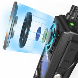
Image 5.1: Channel and Volume Knobs.
This image provides a close-up view of the two rotary knobs located at the top of the radio. The left knob controls power and volume, while the right knob is used for channel selection. Both knobs feature a textured surface for easy grip and rotation.
5.3. Transmitting and Receiving
- To transmit, press and hold the PTT (Push-to-Talk) button on the side of the radio or on the speaker microphone. Speak clearly into the microphone. The status indicator will typically glow red.
- Release the PTT button to stop transmitting and return to receive mode. The status indicator will typically glow green when receiving a signal.
5.4. Group Call Function
The GROUP PTT feature allows for one-key group calling across different channels, useful for announcements or emergency contact.
- Press the 'GROUP/OK' button (located below the LCD screen) to initiate a group call.
- Speak into the microphone while the group call is active.
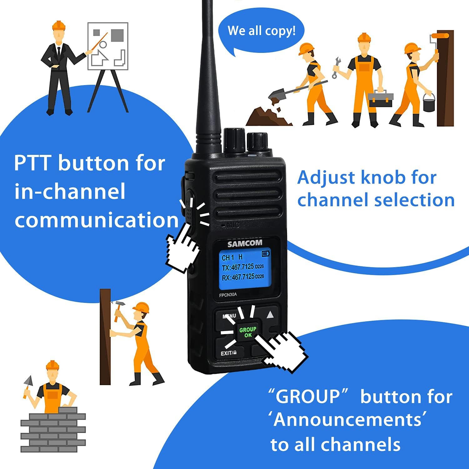
Image 5.2: PTT and Group Button Usage.
This illustration demonstrates the use of the PTT button for in-channel communication and the 'GROUP' button for broadcasting announcements to all channels. It shows individuals in a construction setting communicating effectively using the radio's features.
5.5. Power Modes (High/Low)
The radio supports two power modes to optimize performance and battery life:
- High Power Mode: Provides maximum penetration and range, suitable for environments with obstructions or longer distances.
- Low Power Mode: Conserves battery life, ideal for shorter distances or when maximum power is not required.
Refer to the radio's menu settings (accessed via the MENU button) to switch between High and Low power modes.

Image 5.3: High and Low Power Modes.
This diagram visually explains the concept of high and low power modes. High power mode is depicted with a strong signal emanating from a tall building, indicating enhanced signal penetration. Low power mode is shown with a smaller signal, emphasizing extended battery life. The image also highlights the radio's built-in 1500mAh lithium polymer battery.
5.6. Range Information
The effective communication range varies based on environmental conditions:
- Obstructed Areas: 1-2 miles (e.g., dense urban areas, heavy foliage).
- Partially Obstructed Areas: 3-5 miles (e.g., suburban areas, light tree cover).
- No Obstruction: 5-15 miles (e.g., open fields, line of sight).

Image 5.4: Communication Range Diagram.
This diagram illustrates the typical communication range of the SAMCOM FPCN30A radio under varying environmental conditions. It shows concentric circles representing signal reach over a city landscape, indicating ranges of 1-2 miles in obstructed areas, 3-5 miles in partially obstructed areas, and 5-15 miles in areas with no obstruction. The long antenna is highlighted as a factor in increasing effective range.
6. Maintenance
6.1. General Care
- Keep the radio dry. Exposure to moisture can damage internal circuits.
- Avoid extreme temperatures. Do not store the radio in very hot or cold environments.
- Handle the radio with care. Avoid dropping or subjecting it to strong impacts.
6.2. Cleaning
- Clean the radio's surface with a soft, damp cloth. Do not use harsh chemicals or abrasive cleaners.
- Ensure the charging contacts are clean and free of debris for proper charging.
6.3. Battery Care
- Charge the battery fully before initial use.
- Do not overcharge or deep discharge the battery frequently.
- If the radio will not be used for an extended period, remove the battery and store it in a cool, dry place.
7. Troubleshooting
If you encounter issues with your radio, refer to the following common problems and solutions:
| Problem | Possible Cause | Solution |
|---|---|---|
| Radio does not power on | Battery is depleted or not properly installed. | Charge the battery. Ensure the battery is securely attached. |
| Cannot transmit or receive | Incorrect channel selected. Antenna not attached. Radio out of range. | Verify channel. Attach antenna. Move closer to other radios. |
| Poor audio quality | Low battery. Obstructions. Volume too low. | Charge battery. Move to a clearer area. Adjust volume. |
| Speaker microphone not working | Not properly connected. Damaged cable. | Ensure firm connection. Try another speaker mic if available. |
8. Specifications
Key technical specifications for the SAMCOM FPCN30A Two Way Radio:
| Feature | Specification |
|---|---|
| Item Weight | 2.81 pounds |
| Product Dimensions | 1.81 x 2.36 x 11.14 inches |
| Item Model Number | FPCN30A |
| Batteries | 2 Lithium Polymer batteries required (included) |
| Display Type | LCD |
| Brand | SAMCOM |
| Color | Black |
| Number of Channels | 20 |
| Special Feature | 2 pin K type, work with speaking mic shoulder mic |
| Frequency Range | UHF 406.1-470 MHz |
| Talking Range Maximum | 5 Mile (nominal, varies by obstruction) |
| Voltage | 7 Volts |
| Water Resistance Level | Not Water Resistant |
| FCC ID | 2AIOQ-FPCN30AA |
9. Warranty and Support
9.1. Warranty Information
SAMCOM products offer a lifetime warranty. Please retain your proof of purchase for warranty claims.
9.2. Customer Support
For technical assistance, warranty service, or any questions regarding your SAMCOM FPCN30A Two Way Radio, please contact SAMCOM customer support through the retailer where the product was purchased or visit the official SAMCOM website for contact information.


