
1. Product Overview
The RDL1225B RUILIAN Science inverter fan is a 24V, 0.18A, 120×120×25mm 3-wire fan designed for various applications, particularly in inverters and other electronic systems requiring efficient cooling. This fan is built to provide reliable air circulation to prevent overheating of components.
Key Features:
- Model: RDL1225B
- Dimensions: 120×120×25mm
- Voltage: 24V
- Current: 0.18A
- 3-wire connection for power and speed monitoring (if applicable to the specific 3-wire implementation).
- Original part designed to resolve machine cooling issues.

Figure 1.1: Front view of the RDL1225B inverter fan, highlighting the fan blades and product label.
2. Specifications
| Attribute | Value |
|---|---|
| Brand | ELOMILE |
| Model | RDL1225B |
| Product Dimensions | 4.72 x 0.98 x 4.72 inches (120 x 25 x 120 mm) |
| Voltage | 24 Volts |
| Current | 0.18 Amps |
| Wattage | 1.59 watts |
| Compatible Devices | Inverter |
| Material | Copper (internal components) |
| Number of Items | 1 |
| UPC | 755346731070 |
3. Setup and Installation
3.1 Unpacking
Carefully remove the fan from its packaging. Inspect the fan for any visible damage during transit. Ensure all components, including the fan and its attached wiring, are intact.
3.2 Mounting
The RDL1225B fan is designed for standard mounting in a 120x120mm opening. Use appropriate screws (not included) to secure the fan to the desired surface or enclosure. Ensure the fan is mounted in a way that allows for optimal airflow, considering the intended direction of air movement (intake or exhaust).

Figure 3.1: Side view of the fan, illustrating its profile and mounting points.

Figure 3.2: Rear view of the fan, showing the motor and wire exit point.
3.3 Wiring
The RDL1225B fan features a 3-wire connection. Proper wiring is crucial for safe and correct operation. Refer to the following color code:
- Red Wire: Positive (+24V DC)
- Black Wire: Negative (Ground)
- Blue/Yellow Wire: Tachometer/Speed Sensor Output (provides a signal indicating fan speed, if supported by the connected device).
Connect the wires to the corresponding terminals on your inverter or power supply. Ensure secure connections to prevent loose contacts or short circuits. If you are unsure about the wiring, consult a qualified technician or refer to the manual of the device you are connecting the fan to.
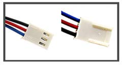
Figure 3.3: Detail of the 3-wire connector.
4. Operation
4.1 Power On/Off
Once properly installed and wired, the fan will begin operation when 24V DC power is supplied to the red and black wires. The fan will stop when power is removed.
4.2 Normal Operation
During normal operation, the fan should produce a consistent airflow and a low, steady hum. The blue/yellow wire will output a pulse signal proportional to the fan's rotational speed, which can be used by compatible monitoring systems.
5. Maintenance
5.1 Cleaning
Periodically inspect the fan blades and housing for dust accumulation. Dust can impede airflow and reduce cooling efficiency. Use a soft brush or compressed air to gently clean the fan blades and grille. Ensure the power is disconnected before cleaning.
5.2 Inspection
Regularly check the fan for any unusual noises, vibrations, or reduced airflow. Ensure all mounting screws remain tight. If the fan exhibits any abnormal behavior, refer to the troubleshooting section.
6. Troubleshooting
| Problem | Possible Cause | Solution |
|---|---|---|
| Fan not spinning | No power, incorrect wiring, faulty fan. | Check power supply (24V DC). Verify wiring connections (Red to +, Black to -). If power and wiring are correct, the fan may be faulty and require replacement. |
| Excessive noise or vibration | Loose mounting, dust accumulation on blades, worn bearings. | Ensure fan is securely mounted. Clean fan blades. If noise persists, the fan bearings may be worn, indicating a need for replacement. |
| Reduced airflow | Dust accumulation, obstruction. | Clean fan blades and grilles. Ensure there are no obstructions blocking the fan's intake or exhaust. |
| Tachometer signal not working | Incorrect wiring of blue/yellow wire, incompatible monitoring system. | Verify the blue/yellow wire is correctly connected to the monitoring input. Ensure your monitoring system is compatible with a 3-wire fan's tachometer output. |
If problems persist after attempting these solutions, please contact customer support.
7. Warranty and Support
This product is covered by a standard manufacturer's warranty against defects in materials and workmanship. Please retain your proof of purchase for warranty claims. For specific warranty terms and conditions, refer to the documentation provided at the time of purchase or contact the seller.
For technical assistance, installation queries, or any other support needs, please contact the seller or manufacturer directly. When contacting support, please provide your product model (RDL1225B) and a detailed description of the issue.