1. Product Overview
The Cisco Catalyst 9300 C9300-24S-E is a 24-port Gigabit Ethernet SFP modular uplink network switch designed for enterprise-level network deployments. It provides high-performance switching capabilities, advanced security features, and network automation for modern business environments. This manual provides essential information for the safe and efficient installation, operation, and maintenance of your switch.
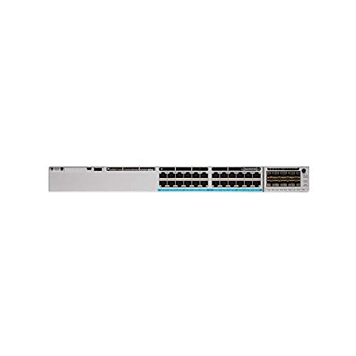
Figure 1: Front view of the Cisco Catalyst 9300 C9300-24S-E Switch. This image displays the 24 SFP ports and modular uplink slots.
2. Safety Information
Read all safety warnings and instructions before installing, operating, or servicing this equipment. Failure to follow these instructions can result in serious injury or equipment damage.
- Electrical Safety: Ensure the power source matches the switch's voltage requirements. Always connect the power cord to a grounded outlet. Do not operate the switch with damaged power cords or plugs.
- Ventilation: Maintain adequate airflow around the switch to prevent overheating. Do not block ventilation openings.
- Handling: This device is heavy. Use proper lifting techniques or assistance when moving or installing.
- Environment: Operate the switch within the specified temperature and humidity ranges. Avoid exposure to moisture or extreme temperatures.
- Servicing: Refer all servicing to qualified service personnel. Do not attempt to open or repair the switch yourself.
3. Package Contents
Verify that your package contains the following items. If any item is missing or damaged, contact your vendor immediately.
- Cisco Catalyst 9300 C9300-24S-E Switch
- AC Power Cord
- Rack-mount Kit (brackets, screws)
- Console Cable (RJ-45 to DB-9)
- Documentation (Quick Start Guide, Safety Information)
4. Physical Description and Components
The C9300-24S-E switch features a robust design with various ports and indicators for network connectivity and status monitoring.
4.1 Front Panel
Figure 2: Detailed view of the switch's front panel, highlighting SFP ports and status LEDs.
- 24 x SFP Ports: For Gigabit Ethernet fiber or copper connectivity using SFP transceivers.
- Modular Uplink Slots: Located on the right side, these slots accommodate optional uplink modules for higher bandwidth connections (e.g., 10G, 25G, 40G, 100G).
- Status LEDs: Indicate system status (SYS), redundant power supply (RPS), port status (STAT), and stack status (STACK).
- USB Type-A Port: For external storage or software upgrades.
- USB Type-C Console Port: For console access and initial configuration.
- RJ-45 Console Port: For traditional console access.
4.2 Rear Panel
Figure 3: Rear view of the switch, showing power supply bays and fan modules.
- Power Supply Bays: Two bays for redundant power supplies.
- Fan Modules: Field-replaceable fan modules for cooling.
- StackWise-1T Ports: (If applicable to the specific model variant) For stacking multiple switches.
5. Setup and Installation
Follow these steps to properly install your Cisco Catalyst 9300 switch.
5.1 Rack Mounting
- Attach the provided rack-mount brackets to the sides of the switch using the included screws.
- Align the switch with the desired rack unit (RU) space in your equipment rack.
- Secure the switch to the rack using the rack screws.
Figure 4: Illustration of the switch being mounted into a standard equipment rack.
5.2 Power Connection
- Insert the AC power cord into the power supply module on the rear of the switch.
- Connect the other end of the power cord to a grounded AC power outlet.
- If using redundant power supplies, repeat for the second power supply.
5.3 Network Connections
- Insert appropriate SFP transceivers into the 24 SFP ports as needed.
- Connect fiber optic or copper cables from your network devices (servers, workstations, other switches) to the SFP transceivers.
- Install any optional uplink modules into the modular uplink slots and connect them to your core network infrastructure.
6. Operating Instructions
6.1 Powering On
Once power is connected, the switch will automatically power on. Observe the system status LEDs on the front panel. The SYS LED should turn green after the boot sequence completes.
6.2 Initial Configuration
For initial configuration, connect a console cable from your computer to the switch's console port (either USB-C or RJ-45). Use a terminal emulation program (e.g., PuTTY, Tera Term) with the following settings:
- Baud Rate: 9600
- Data Bits: 8
- Parity: None
- Stop Bits: 1
- Flow Control: None
Follow the on-screen prompts to complete the initial setup wizard. For advanced configurations, refer to the Cisco IOS XE documentation for Catalyst 9300 Series switches.
6.3 LED Indicators
| LED | Color/State | Description |
|---|---|---|
| SYS (System) | Green (Solid) | System is operating normally. |
| Amber (Solid) | System fault or error. | |
| STAT (Port Status) | Green (Solid) | Link established. |
| Green (Flashing) | Activity on port. | |
| Off | No link or port disabled. |
7. Maintenance
Regular maintenance ensures optimal performance and longevity of your switch.
- Cleaning: Periodically clean the exterior of the switch with a soft, dry cloth. Ensure ventilation openings are free from dust and debris. Do not use liquid cleaners directly on the switch.
- Firmware Updates: Regularly check the Cisco support website for the latest firmware updates. Applying updates can improve performance, add features, and address security vulnerabilities. Follow Cisco's recommended procedures for firmware upgrades.
- Environmental Monitoring: Ensure the operating environment remains within specified temperature and humidity ranges to prevent hardware stress.
8. Troubleshooting
This section provides solutions to common issues you might encounter.
8.1 No Power
- Check Power Cord: Ensure the power cord is securely connected to both the switch and the power outlet.
- Verify Outlet: Test the power outlet with another device to confirm it is functional.
- Power Supply Status: Check the power supply LEDs on the rear of the switch. If off or amber, the power supply may be faulty or not receiving power.
8.2 No Link on Port
- Cable Connection: Ensure the network cable is securely connected to both the switch port and the connected device.
- Cable Integrity: Test the cable with another device or replace it to rule out a faulty cable.
- Transceiver: If using SFP transceivers, ensure they are properly seated and compatible with both the switch and the connected device.
- Port Configuration: Verify that the switch port is enabled and correctly configured (e.g., speed, duplex settings).
8.3 Network Connectivity Issues
- IP Configuration: Verify IP addresses, subnet masks, and gateway settings on connected devices and the switch.
- VLANs: If using VLANs, ensure ports are assigned to the correct VLANs and trunk links are properly configured.
- Firewall/ACLs: Check for any Access Control Lists (ACLs) or firewall rules on the switch that might be blocking traffic.
- Software Issues: Consider restarting the switch or checking the system logs for error messages.
9. Specifications
Key technical specifications for the Cisco Catalyst 9300 C9300-24S-E switch:
| Feature | Detail |
|---|---|
| Model Number | C9300-24S-E |
| Brand | Cisco |
| Interface Type | SFP |
| Number of Ports | 24 |
| Compatible Devices | Desktop, Laptop, Printer |
| Product Dimensions | 21.65 x 22.44 x 9.45 inches |
| Case Material | Plastic |
| Upper Temperature Rating | 40 Degrees Celsius |
| Manufacturer | CISCO SYSTEMS - ENTERPRISE |
| UPC | 656942062790 |
10. Warranty and Support
This Cisco product is typically covered by a limited hardware warranty provided by Cisco Systems. The exact terms and duration of the warranty may vary based on your region and purchase agreement. For detailed warranty information, please refer to the official Cisco warranty statements available on their website or contact your authorized Cisco reseller.
For technical support, documentation, and software downloads, visit the official Cisco Support website. You will need your product serial number to register and access certain support resources.
- Cisco Support Website: www.cisco.com/go/support
- Contact Support: Refer to the Cisco website for regional contact information.


