
Flysky Z43139
Flysky FS-GT2F 2CH 2.4GHz Transmitter and A3 Receiver Instruction Manual
Model: Z43139
1. Introduction
This manual provides detailed instructions for the operation and maintenance of your Flysky FS-GT2F 2-channel 2.4GHz radio system, including the FS-A3 receiver. This system is designed for use with RC cars and boats, offering reliable control and performance. Please read this manual thoroughly before operating the device to ensure safe and correct usage.
2. Product Overview
The Flysky FS-GT2F is a 2-channel 2.4GHz transmitter utilizing AFHDS 2A/AFHDS modulation for stable and interference-free control. It comes paired with an FS-A3 receiver.
2.1. Transmitter Components

Figure 1: Front view of the Flysky FS-GT2F Transmitter. This image shows the steering wheel, throttle trigger, and the main body of the transmitter.

Figure 2: Side view of the Flysky FS-GT2F Transmitter. This image highlights the ergonomic grip and the antenna.
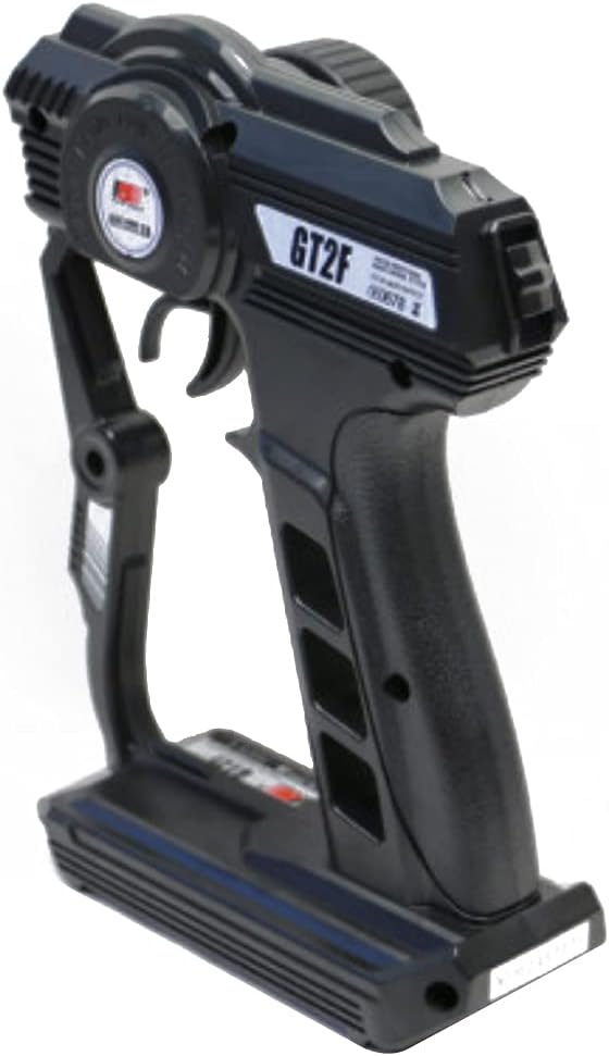
Figure 3: Angled view of the Flysky FS-GT2F Transmitter. This perspective shows the overall design and button placement.

Figure 4: Top view of the Flysky FS-GT2F Transmitter. This view displays the LED indicators and control knobs.
- Steering Wheel: Controls the steering of your RC model.
- Throttle Trigger: Controls the forward and reverse movement (throttle/brake).
- LED Indicators: Provide status information (e.g., power, binding status, low voltage).
- Power Switch: Turns the transmitter on/off.
- Trim Dials: Adjust steering and throttle neutral points.
- D/R (Dual Rate) Switch: Adjusts the maximum steering angle.
- DSC Port: Micro-USB port for simulator connection.
- Antenna: 26mm length for 2.4GHz signal transmission.
2.2. FS-A3 Receiver
The FS-A3 is a compact 3-channel receiver designed to work seamlessly with the FS-GT2F transmitter. It features standard servo connections and a bind port.
3. Setup
3.1. Battery Installation
- Open the battery compartment cover located at the bottom of the transmitter.
- Insert four (4) 1.5V AA batteries (not included) into the compartment, ensuring correct polarity.
- Close the battery compartment cover securely.
Note: The transmitter requires 6V DC power (4 x 1.5AA batteries). Ensure batteries are fully charged or new for optimal performance.
3.2. Power On
- Ensure the throttle trigger is in the neutral position and the steering wheel is centered.
- Toggle the power switch on the transmitter to the "ON" position. The LED indicator should light up.
3.3. Binding the Transmitter and Receiver
Binding is the process of linking the transmitter and receiver so they communicate exclusively with each other. The FS-GT2F and FS-A3 receiver are pre-bound from the factory. If re-binding is necessary, follow these steps:
- Connect the bind cable to the B/VCC port on the receiver.
- Connect power to the receiver (e.g., from an ESC or separate battery). The receiver's LED should flash rapidly.
- Press and hold the BIND button on the transmitter while turning it on.
- The transmitter's LED should flash slowly, indicating it's in binding mode.
- Once the receiver's LED stops flashing and remains solid, the binding is successful.
- Release the BIND button on the transmitter and turn off both the transmitter and receiver.
- Remove the bind cable from the receiver.
- Turn on the transmitter, then the receiver. The system should now be bound and ready for use.
4. Operating Instructions
4.1. Basic Operation
- Steering: Turn the steering wheel left or right to control the direction of your model.
- Throttle: Pull the throttle trigger back for forward movement. Push the trigger forward for braking or reverse.
4.2. Adjusting Trims
Trim dials are used to make fine adjustments to the neutral position of the steering and throttle channels. If your model pulls to one side or moves slightly forward/backward when the controls are centered, use the trim dials to correct it.
- ST.TRIM (Steering Trim): Adjusts the steering neutral point.
- TH.TRIM (Throttle Trim): Adjusts the throttle neutral point.
4.3. Dual Rate (D/R)
The D/R switch allows you to adjust the maximum steering angle. This is useful for tuning the sensitivity of the steering for different driving conditions or personal preference.
4.4. End Point Adjustment (EPA)
EPA allows you to set the maximum travel for each servo channel. This prevents servos from over-traveling and potentially damaging them or the model.
4.5. ABS (Anti-lock Braking System)
The ABS function simulates an anti-lock braking system, preventing wheels from locking up during hard braking, which can improve control and reduce tire wear.
4.6. SVC (Smart Vehicle Control)
SVC provides enhanced stability and control for your vehicle, especially during high-speed maneuvers or on slippery surfaces.
5. Maintenance
- Keep the transmitter and receiver clean and free from dust and dirt. Use a soft, dry cloth for cleaning.
- Avoid exposing the system to extreme temperatures, direct sunlight, or moisture.
- Remove batteries from the transmitter if it will not be used for an extended period to prevent leakage.
- Regularly check all connections for secure fit.
6. Troubleshooting
- No Power: Check battery installation and ensure batteries are charged.
- No Control/Loss of Signal:
- Ensure the transmitter and receiver are properly bound. Re-bind if necessary.
- Check the distance between the transmitter and receiver. The RF range is 2.4055-2.475GHz.
- Verify all connections between the receiver, servos, and ESC are secure.
- Check for interference from other 2.4GHz devices.
- Erratic Movement: Check for loose connections, interference, or damaged components. Ensure trims are centered.
- Low Voltage Warning: If the transmitter's LED flashes, replace or recharge the batteries immediately. Low voltage warning is below 4.2V.
7. Specifications
| Feature | Specification |
|---|---|
| Channels | 2 |
| Model Type | Car/Boat |
| RF Range | 2.4055-2.475GHz |
| RF Power | <20dBm |
| RF Channel | 140 |
| Bandwidth | 500KHz |
| 2.4GHz System | AFHDS 2A/AFHDS |
| Modulation Type | GFSK |
| Stick Resolution | 1024 |
| Low Voltage Warning | <4.2V |
| DSC Port | Micro-USB PPM |
| Steering Range | 70° (L:35° R: 35°) |
| Throttle Range | 45° (F: 30° B: 15°) |
| Chargeable | No |
| Antenna Length | 26mm |
| Weight | 323g |
| Power | 6V DC (4 x 1.5AA batteries) |
| Display | LED indicators |
| Size | 196 x 150 x 80 mm |
| Color | Black |
| Certificates | CE0678, FCC |
8. Warranty and Support
For warranty information and technical support, please refer to the official Flysky website or contact your retailer. Keep your purchase receipt as proof of purchase.
Ask a question about this manual
Ask about setup, troubleshooting, compatibility, parts, safety, or missing instructions. Manuals+ will review the question and use this page’s manual context to help answer it.