1. Introduction
The ELEGOO MEGA R3 ATmega 2560 Microcontroller Board is a powerful and versatile development platform designed for a wide range of electronic projects. It is fully compatible with the Arduino IDE, making it an excellent choice for both beginners and experienced users in electronics and programming. This board features an ATmega 2560 microcontroller, offering extensive I/O capabilities and memory for complex applications.

Image 1: The ELEGOO MEGA R3 ATmega 2560 Microcontroller Board with its included USB cable.
2. Setup
2.1 Unpacking
Upon opening the package, ensure all components are present:
- 1 x ELEGOO MEGA R3 ATmega 2560 Microcontroller Board
- 1 x USB Cable

Image 2: The ELEGOO MEGA R3 board and USB cable as received in its packaging.
2.2 Software Installation
To begin using your ELEGOO MEGA R3 board, you need to install the Arduino IDE (Integrated Development Environment). This software allows you to write, compile, and upload code (sketches) to the board.
- Download the latest version of the Arduino IDE from the official Arduino website: www.arduino.cc/en/software.
- Follow the installation instructions provided on the Arduino website for your specific operating system.
- During installation, ensure that all necessary drivers are selected for installation. These drivers are crucial for your computer to recognize the ELEGOO MEGA R3 board.
2.3 Connecting the Board
Connect the ELEGOO MEGA R3 board to your computer using the provided USB cable. The USB connection serves both for power supply and data communication (uploading sketches and serial communication).
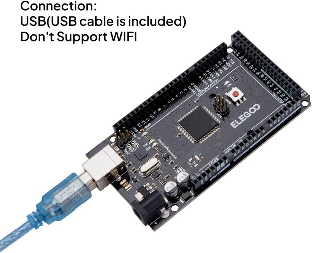
Image 3: The ELEGOO MEGA R3 board connected to a computer via the USB cable for power and data transfer.
Alternatively, the board can be powered via an external power supply (7-12V DC recommended, 6-20V limits) connected to the DC barrel jack. This is useful for standalone projects not connected to a computer.
3. Operating Instructions
3.1 Programming with Arduino IDE
Once the Arduino IDE is installed and your board is connected:
- Open the Arduino IDE.
- Go to Tools > Board and select "Arduino/Genuino Mega or Mega 2560".
- Go to Tools > Port and select the serial port corresponding to your connected ELEGOO MEGA R3 board.
- You can now write your code (sketch) in the IDE. A simple test is to load the "Blink" example from File > Examples > 01.Basics > Blink.
- Click the "Upload" button (right arrow icon) to compile and upload the sketch to your board. The RX/TX LEDs on the board will blink during the upload process.
3.2 Digital I/O Pins
The ELEGOO MEGA R3 board has 54 digital input/output pins (0-53), with 15 of these supporting PWM (Pulse Width Modulation) output. These pins can be configured as either inputs or outputs to interact with various electronic components like LEDs, buttons, and sensors.
3.3 Analog Input Pins
The board includes 16 analog input pins (A0-A15). These pins are used to read analog sensor values, converting them into digital values that the microcontroller can process.
3.4 Communication Interfaces
The ELEGOO MEGA R3 supports several communication protocols:
- Serial Communication: Multiple hardware serial ports (UART) are available for communication with other devices or for debugging via the Serial Monitor in the Arduino IDE.
- SPI (Serial Peripheral Interface): Used for high-speed communication with peripherals.
- I2C (Inter-Integrated Circuit): A two-wire interface for connecting multiple low-speed peripheral devices. The SDA and SCL pins are located near the AREF pin.

Image 4: Detailed diagram illustrating the various components and pin functions of the ELEGOO MEGA R3 board, including digital I/O, analog inputs, communication interfaces, and power regulators.
4. Maintenance
4.1 Cleaning
To maintain optimal performance, keep the board clean and free from dust and debris. Use a soft, dry brush or compressed air to gently clean the surface. Avoid using liquids or abrasive materials.
4.2 Storage
Store the ELEGOO MEGA R3 board in a dry, cool environment, away from direct sunlight and extreme temperatures. It is recommended to store it in an anti-static bag to prevent electrostatic discharge damage.
4.3 Firmware Updates
Periodically check the official Arduino website or ELEGOO's support page for any available firmware updates for the ATmega 2560 microcontroller or the ATmega16U2 USB-to-serial converter. Follow the provided instructions carefully to update the firmware, if necessary.
5. Troubleshooting
5.1 Board Not Recognized by Computer
- Check USB Cable: Ensure the USB cable is securely connected to both the board and the computer. Try a different USB port or cable.
- Driver Installation: Verify that the USB drivers were installed correctly during the Arduino IDE setup. Reinstalling the drivers might resolve the issue.
- IDE Port Selection: In the Arduino IDE, go to Tools > Port and ensure the correct serial port is selected. If no port appears, the drivers may not be installed or the board is not recognized.
5.2 Sketch Upload Failure
- Correct Board and Port: Double-check that the correct board (Arduino/Genuino Mega or Mega 2560) and serial port are selected in the Arduino IDE's Tools menu.
- Code Errors: Review your sketch for any compilation errors. The Arduino IDE will display error messages in the console.
- Bootloader: If the board is new or has been previously used with custom firmware, ensure the bootloader is intact. In rare cases, the bootloader might need to be re-flashed.
5.3 Power Issues
- Power LED: Check if the power LED on the board illuminates when connected to USB or an external power supply. If not, verify the power source.
- External Power Supply: If using an external power supply, ensure it provides the correct voltage (7-12V DC) and sufficient current.
- USB Fuse: The board has a resettable fuse for USB protection. If the board was short-circuited, this fuse might have tripped. Disconnect power, wait a few moments, and reconnect.
6. Specifications
| Feature | Specification |
|---|---|
| Microcontroller | ATmega 2560 |
| Operating Voltage | 5V |
| Input Voltage (Recommended) | 7-12V |
| Input Voltage (Limits) | 6-20V |
| Digital I/O Pins | 54 (15 provide PWM output) |
| Analog Input Pins | 16 |
| DC Current per I/O Pin | 40 mA |
| DC Current for 3.3V Pin | 50 mA |
| Flash Memory | 256 KB (8 KB used by bootloader) |
| SRAM | 8 KB |
| EEPROM | 4 KB |
| Clock Speed | 16 MHz |
| Dimensions | 107.6 x 53.4 x 18 mm (4.24 x 2.1 x 0.71 inches) |
| Item Weight | 36.29 grams (1.28 ounces) |

Image 5: The ELEGOO MEGA R3 board with its physical dimensions clearly indicated.
7. Warranty and Support
For warranty information and technical support, please refer to the official ELEGOO website or contact ELEGOO customer service directly. Keep your purchase receipt for warranty claims.
Official ELEGOO Website: www.elegoo.com


