1. Introduction
This manual provides essential information for the safe and effective operation, maintenance, and troubleshooting of your Stanley 460276 VIP Multi 160 3-in-1 Welding Machine. Please read this manual thoroughly before using the product and retain it for future reference.
The Stanley VIP Multi 160 is a versatile inverter-based welding machine offering three welding processes: MMA (Manual Metal Arc) for electrodes, MIG GAS for solid wire, and MIG NO GAS for flux-cored wire. Its inverter technology ensures features like Anti-stick, Arc Force, and Hot Start for improved welding performance and ease of use.
2. Safety Information
WARNING: Welding can be dangerous. Always follow safety precautions to prevent serious injury or death.
- Electric Shock: Can kill. Do not touch live electrical parts. Wear dry welding gloves and protective clothing. Ensure the work area is dry.
- Fumes and Gases: Can be hazardous to your health. Keep your head out of the fumes. Use ventilation or exhaust to remove fumes and gases from the breathing zone.
- Arc Rays: Can burn eyes and skin. Wear a welding helmet with a proper shade filter. Wear protective clothing to protect skin.
- Fire and Explosion: Welding sparks can cause fire or explosion. Keep flammable materials away from the welding area. Have a fire extinguisher readily available.
- Hot Parts: Can cause severe burns. Allow welding equipment to cool before touching.
- Magnetic Fields: Can affect pacemakers. Consult your doctor before operating.
- Always disconnect power before servicing.
- Ensure proper grounding of the welding machine.
3. Package Contents
Verify that all items listed below are present and undamaged upon unpacking:
- Stanley VIP Multi 160 Welding Machine
- Electrode Holder with Cable
- Ground Clamp with Cable
- MIG Torch
- CE Fixed Welding Mask
- Wire Brush / Chipping Hammer
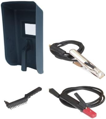
Figure 3.1: Included accessories: welding mask, ground clamp, electrode holder, MIG torch, and wire brush/chipping hammer.
4. Product Overview
The Stanley VIP Multi 160 is a compact and powerful 3-in-1 inverter welding machine. Familiarize yourself with its main components and controls.

Figure 4.1: Front view of the Stanley VIP Multi 160 welding machine, showing control panel, cable connections, and handle.
4.1 Main Components
- Control Panel: Digital display and knobs for adjusting welding parameters.
- Power Switch: Located on the rear of the unit.
- Cable Connections: Sockets for electrode holder, ground clamp, and MIG torch.
- Wire Feed Mechanism: Internal compartment for welding wire spool.
- Cooling Fan: Ensures proper temperature regulation during operation.
4.2 Control Panel (Refer to Figure 4.1)
- Digital Display: Shows current welding parameters (e.g., amperage, voltage, wire speed).
- Mode Selector: Button or knob to switch between MMA, MIG GAS, and MIG NO GAS modes.
- Current/Voltage Adjustment Knob: Adjusts welding current (MMA) or voltage (MIG).
- Wire Feed Speed Adjustment Knob: Adjusts the speed of wire delivery (MIG).
5. Setup
5.1 Power Connection
- Ensure the welding machine's power switch is in the OFF position.
- Connect the power cable to a grounded 230V/50Hz power outlet. The machine is compatible with a 7.5 kVA generator.
- Verify the power outlet can supply the required current (up to 5.5 kVA absorbed power at 60% duty cycle).
5.2 Ground Clamp Connection
- Connect the ground clamp cable to the designated negative (-) terminal on the welding machine.
- Securely attach the ground clamp to the workpiece or a clean, bare metal part of the welding table. Ensure good electrical contact.
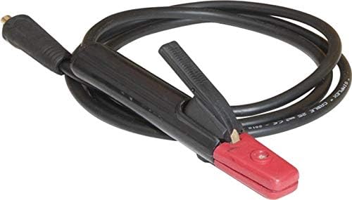
Figure 5.1: The ground clamp, essential for completing the welding circuit.
5.3 MMA (Electrode) Setup
- Connect the electrode holder cable to the designated positive (+) terminal on the welding machine.
- Insert the appropriate electrode (rutile, basic, or cellulosic, up to 4mm diameter) into the electrode holder.
- Select MMA mode on the control panel.

Figure 5.2: The electrode holder, used for MMA welding.
5.4 MIG (Wire) Setup
- Open the wire spool compartment.
- Install the appropriate welding wire spool (solid wire or flux-cored wire, 0.6-1.0mm diameter).
- Thread the wire through the wire feed mechanism and into the MIG torch liner.
- Connect the MIG torch to the designated connector on the welding machine.
- For MIG GAS welding: Connect a gas cylinder (e.g., Argon, CO2, or mixed gas) to the gas inlet on the machine and ensure the gas flow is set correctly. Select MIG GAS mode.
- For MIG NO GAS (Flux-Cored) welding: No external gas cylinder is required. Select MIG NO GAS mode.

Figure 5.3: The MIG torch, used for wire welding processes.
6. Operating Instructions
Always wear appropriate personal protective equipment (PPE), including a welding helmet, gloves, and protective clothing, before operating the machine.

Figure 6.1: The CE fixed welding mask provided for eye and face protection during welding.
6.1 General Operation Steps
- Ensure all connections are secure and correct for the chosen welding process.
- Turn on the welding machine using the power switch.
- Select the desired welding mode (MMA, MIG GAS, or MIG NO GAS) on the control panel.
- Adjust the welding current (for MMA) or voltage and wire feed speed (for MIG) according to the material thickness and type of electrode/wire. Refer to welding charts for recommended settings.
- Begin welding, maintaining a stable arc and proper technique.
- After welding, turn off the machine and allow it to cool.
6.2 MMA Welding (Electrode)
- Current Range: 10-160A.
- Electrode Diameter: Up to 4mm.
- Features: Hot Start for easy arc ignition, Arc Force for stable arc, Anti-stick to prevent electrode sticking.
- Procedure: Strike the arc by lightly touching and quickly lifting the electrode from the workpiece. Maintain a consistent arc length and travel speed.
6.3 MIG Welding (Gas / No Gas)
- Current Range: 10-160A.
- Wire Diameter: Solid wire (SG2, Stainless Steel) 0.6-1.0mm; Flux-cored wire 0.8-0.9mm.
- Wire Feed Speed: Continuously adjustable.
- Procedure: Position the MIG torch at the correct angle and distance from the workpiece. Press the trigger to start the wire feed and arc. Maintain a steady travel speed and torch angle.
7. Maintenance
Regular maintenance ensures the longevity and safe operation of your welding machine.
- Cleaning: Regularly clean the machine's exterior with a dry cloth. Use compressed air to clear dust from internal components, ensuring the machine is unplugged.
- Cable Inspection: Periodically inspect all cables (power, ground, electrode, MIG torch) for cuts, fraying, or damage. Replace damaged cables immediately.
- MIG Torch Maintenance: Clean the contact tip and gas nozzle regularly. Replace worn contact tips. Ensure the wire liner is free of obstructions.
- Electrode Holder/Ground Clamp: Keep connections clean and tight.
- Storage: Store the welding machine in a dry, clean environment, away from dust and moisture.
8. Troubleshooting
This section addresses common issues you might encounter. For problems not listed here, contact customer support.
| Problem | Possible Cause | Solution |
|---|---|---|
| No power to the machine. | Power cable unplugged, circuit breaker tripped, faulty power switch. | Check power cable connection, reset circuit breaker, contact service if switch is faulty. |
| No arc (MMA). | Poor ground connection, incorrect current setting, wet electrode, faulty electrode holder. | Ensure ground clamp is on clean metal, adjust current, use dry electrodes, check electrode holder. |
| Wire not feeding (MIG). | Wire tangled, contact tip clogged, wire feed roller tension incorrect, motor fault. | Check wire spool, clean contact tip, adjust roller tension, contact service if motor faulty. |
| Poor weld quality. | Incorrect settings (current, voltage, wire speed), improper technique, contaminated workpiece, wrong gas (MIG GAS). | Adjust settings, improve technique, clean workpiece, verify gas type and flow. |
| Overheating protection activated. | Exceeded duty cycle, insufficient ventilation. | Allow machine to cool down, ensure adequate airflow around the unit. |
9. Specifications
| Feature | Specification |
|---|---|
| Model | Stanley 460276 VIP Multi 160 |
| Welding Processes | MMA (Electrode), MIG GAS (Solid Wire), MIG NO GAS (Flux-Cored Wire) |
| Input Voltage | 230V / 50Hz |
| Welding Current Range (MMA/MIG) | 10 - 160A |
| No-Load Voltage | 72V |
| Duty Cycle (at 20°C) | 60% at 160A |
| Duty Cycle (EN60974-1 at 40°C) | 20% at 160A |
| Max Electrode Diameter | 4mm (Rutile, Basic, Cellulosic) |
| Wire Diameter (Solid) | 0.6 - 1.0mm (SG2, Stainless Steel) |
| Wire Diameter (Flux-Cored) | 0.8 - 0.9mm |
| Absorbed Power (at 60%) | 5.5 kVA |
| Generator Compatibility | 7.5 kVA |
| Protection Class | IP21S |
| Dimensions (L x W x H) | 63 x 24 x 43.5 cm |
| Weight | 13.7 kg |
| Manufacturer | Mecafer |
| Country of Origin | France |
10. Warranty and Support
Information regarding warranty coverage for the Stanley 460276 VIP Multi 160 welding machine is typically provided at the point of purchase or within separate documentation included with the product. Please refer to your purchase receipt or contact the retailer for specific warranty terms and conditions.
For technical support, spare parts, or service inquiries, please contact the manufacturer, Mecafer, or an authorized Stanley service center. Information on spare parts availability is not provided in the product specifications.


