
Leadzm TA-10000
Leadzm TA-10000 Outdoor Dual-Band Antenna User Manual
Model: TA-10000
Introduction
This user manual provides comprehensive instructions for the installation, operation, and maintenance of your Leadzm TA-10000 110V 40-860MHz 20±3dB 350° Rotation UV Dual-Band Outdoor Antenna. This antenna is designed for optimal signal reception, offering a robust and reliable solution for your television viewing needs. Please read this manual thoroughly before installation and use to ensure proper function and safety.

Figure 1: Leadzm TA-10000 Outdoor Dual-Band Antenna. This image shows the complete antenna unit, featuring its black, streamlined design and the central rotating mechanism.
Package Contents
Before proceeding with installation, please verify that all components listed below are present in your package.
- 1 x Antenna (Main Body and Signal Receiving Body)
- 1 x Bracket (Includes 40ft Coaxial Cable)
- 1 x Amplifier Power Supply
- 1 x Remote Control
- 1 x U-shaped Hoop
- 1 x Instruction Manual (this document)

Figure 2: What's in the Packing Box. This image displays the main antenna unit, remote control, power supply, and the included 10-meter coaxial cable, illustrating all components provided in the product package.
Product Features and Components
The Leadzm TA-10000 antenna incorporates several key features for enhanced performance and durability.
- U-band Receiving Unit: Optimized for Ultra High Frequency (UHF) signal reception.
- V-band Receiving Unit: Optimized for Very High Frequency (VHF) signal reception.
- All Copper Motor: Ensures smooth and reliable 350° rotation for optimal signal alignment.
- Built-in Signal Amplifier: Boosts weak signals for improved reception quality.
- Environmental Protection ABS: Durable and weather-resistant material for outdoor use.
- Support Fixed Tooth Clamp: Provides a secure mounting point for installation.

Figure 3: Structure Diagram. This diagram labels the key internal and external components of the antenna, including the U-band and V-band receiving units, all copper motor, built-in signal amplifier, environmental protection ABS casing, and the support fixed tooth clamp.

Figure 4: Built-In Signal Amplifier. This image highlights the antenna's built-in signal amplifier, indicating its capability to receive signals from a maximum distance of 150 miles, enhancing reception over longer ranges.
Setup and Installation
Proper installation is crucial for optimal performance. It is recommended to install the antenna in a high position, such as on a roof, to avoid signal obstruction from buildings or mountains.
1. Mounting the Antenna
The antenna can be mounted using the included bracket and U-shaped hoop to a suitable pole or J-pole mount.
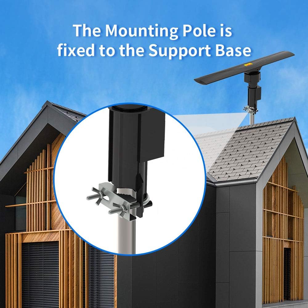
Figure 5: Mounting Pole Installation. This image illustrates how the antenna's mounting pole is securely fixed to a support base using the provided clamp, typically on a rooftop or elevated structure.

Figure 6: J-Pole Mount Installation. This image demonstrates the antenna mounted on a J-pole, showing the bracket attachment points for secure fastening to a wall or roof fascia.
2. Connecting the Coaxial Cable
Connect the 40ft coaxial cable from the antenna to the amplifier power supply unit. Then, connect the amplifier power supply unit to your television or set-top box. Ensure all connections are tight and secure.
3. Power Connection
Plug the amplifier power supply into a standard AC110V/60Hz electrical outlet.
Operation
Once installed and powered, you can operate the antenna using the remote control.
1. Remote Control Functions
The remote control allows you to rotate the antenna 350° to find the best signal reception. Point the remote control towards the amplifier power supply unit for effective communication. The remote controlled distance is ≤5m.
2. Scanning for Channels
After connecting the antenna and powering it on, perform a channel scan on your television or set-top box. Refer to your TV's instruction manual for specific steps on how to perform a channel scan. Rotate the antenna using the remote control and re-scan channels to optimize reception for different broadcast towers.
Specifications
| Feature | Value |
|---|---|
| Frequency | 40-860 MHz |
| VHF Gain | 20±3dB |
| UHF Gain | 28-30dB |
| Max Rotation | 350° |
| Channel Range | 1~69 |
| Impedance | 75 Ω |
| Power Consumption | 3W |
| Power Supply | AC110V/60Hz |
| Rotation Speed | 4-6 rounds/min |
| Remote Controlled Distance | ≤5m |
| Standing Wave Ratio | ≤1.5 |
| Model | TA-10000A |
| Color | Black |
| Weight | 41.59oz / 1179g (2.6 Pounds) |
| Dimensions (L x W x H) | (23.22 x 3.35 x 4.33) inches / (59 x 8.5 x 11) cm |

Figure 7: Antenna Dimensional Drawing. This technical drawing provides precise measurements of the antenna's length, width, and height, useful for planning installation space.
Troubleshooting
- No Signal / Poor Reception:
- Ensure all cable connections are secure.
- Verify the amplifier power supply is plugged in and receiving power.
- Rotate the antenna using the remote control to different directions and perform a channel scan after each adjustment.
- Ensure the antenna is installed in the highest possible location, free from obstructions like buildings, trees, or mountains.
- Check the remote control batteries.
- Remote Control Not Working:
- Ensure there are no obstructions between the remote control and the amplifier power supply unit.
- Replace the batteries in the remote control.
- Ensure you are within the effective remote control distance (≤5m).
Maintenance
The Leadzm TA-10000 antenna is designed for durability and requires minimal maintenance.
- Regular Inspection: Periodically check the antenna and its mounting hardware for any signs of wear, corrosion, or loosening, especially after severe weather conditions.
- Cleaning: If necessary, gently clean the antenna's exterior with a soft, damp cloth. Do not use harsh chemicals or abrasive cleaners.
- Cable Integrity: Ensure the coaxial cable remains free from kinks, cuts, or damage.
Warranty and Support
For warranty information or technical support, please refer to the contact details provided with your purchase documentation or visit the official Leadzm website. Keep your purchase receipt as proof of purchase for warranty claims.
Ask a question about this manual
Ask about setup, troubleshooting, compatibility, parts, safety, or missing instructions. Manuals+ will review the question and use this page’s manual context to help answer it.