
EPEVER Tracer1206
EPEVER MPPT Solar Charge Controller User Manual
Model: Tracer1206 (BLE-004) | Brand: EPEVER
1. Introduction
This manual provides detailed instructions for the installation, operation, and maintenance of your EPEVER MPPT Solar Charge Controller Tracer1206. Please read this manual thoroughly before installation and use to ensure optimal performance and safety.
Important Safety Information:
- Always connect the battery first before connecting the solar panel or load.
- Ensure correct polarity for all connections.
- Do not use electric screwdrivers for terminal connections.
- Refer to local electrical codes and regulations for installation.
2. Product Overview
The EPEVER MPPT Solar Charge Controller Tracer1206 is designed to efficiently manage power from your solar panels to charge various battery types, including lead-acid (sealed, gel/AGM, flooded) and lithium batteries. It features advanced Maximum Power Point Tracking (MPPT) technology for high efficiency.
2.1 Key Features
- 10A Charge/Discharge Current.
- 12V/24V Battery DC system auto-identification.
- Max PV input power: 130W/12V battery, 260W/24V battery.
- Max PV voltage: 60V.
- Common Negative ground design.
- Compatible with Lead-acid (Sealed, GEL/AGM, Flooded) and Lithium batteries.
- Four load control modes: manual, light ON/OFF, light On+Timer, and test mode.
- High tracking efficiency (>99.5%) and peak conversion efficiency (98%).
- Backlight LCD display for real-time data and parameter setting.
- PC software support (Windows only) and MT50 compatibility.
- Comprehensive safety protections: PV Over Current/Power, PV Reverse Polarity, Night Reverse Charging, Battery Over Discharge, Load Short Circuit, and more.
2.2 Product Components

Figure 1: Labeled components of the Tracer1206 controller, showing the LCD display, select and enter buttons, solar panel terminals, battery terminals, load terminals, temperature sensor port, and RJ45 communication port.

Figure 2: Product dimensions of the Tracer 1206AN controller, measuring 172 cm in height, 139 cm in width, and 44 cm in depth.

Figure 3: LCD display showing various parameters such as PV input, charging current, power generation, load work mode, battery voltage, battery current, discharge capacity, discharge current, and temperature.
3. Installation and Setup
Follow these steps carefully for proper installation. Always ensure all power sources are disconnected before making any connections.
3.1 Connection Sequence
WARNING: Always connect the battery first!
- Connect the Battery: Loosen the screws on the battery terminals. Connect the positive (+) and negative (-) battery cables to the corresponding terminals on the controller. Ensure correct polarity.
- Connect the Solar Panel (PV Array): Loosen the screws on the solar panel terminals. Connect the positive (+) and negative (-) solar panel cables to the corresponding terminals. Verify correct polarity.
- Connect the Load: Loosen the screws on the load terminals. Connect your DC load to the corresponding terminals.
Disconnection Sequence:
- Disconnect the Load.
- Disconnect the Solar Panel (PV array).
- Disconnect the Battery.

Figure 4: Comprehensive connection diagram illustrating the proper wiring sequence for the battery, solar panel, and DC/AC loads with the EPEVER solar charge controller.

Figure 5: Front view of the EPEVER MPPT Solar Charge Controller Tracer1206, highlighting the main unit and the included temperature sensor connector.

Figure 6: Close-up view of the green terminal block for the temperature sensor, which connects to the controller to provide accurate battery temperature readings for optimized charging.
3.2 Unboxing and Initial Setup Video
Video 1: Official unboxing and setup guide for the EPEVER MPPT Solar Charge Controller, demonstrating initial connection steps and basic operation. This video is provided by Orico Solar, a seller of EPEVER products.
4. Operating Instructions
4.1 Setting Battery Type
The controller supports various battery types. It is crucial to set the correct battery type for optimal charging and battery longevity.
- Press the "ENTER" button and hold for 5 seconds under the battery voltage interface.
- Press the "SELECT" button when the battery type interface is flashing to cycle through options (Sealed, Gel/AGM, Flooded, Lithium, User).
- Press the "ENTER" button to confirm the selected battery type.
CAUTION: For "User" type, please refer to Chapter 3 of the full user manual for detailed battery control voltage settings.
4.2 Setting Load Working Mode
The controller offers different load working modes to suit various applications.
- Press the "ENTER" button and hold for 5 seconds under the load mode interface.
- Press the "SELECT" button when the load mode interface is flashing to cycle through options (e.g., 17 for Manual Mode, 0 for Light ON/OFF, 1-15 for Light On+Timer, 2n for Test Mode).
- Press the "ENTER" button to confirm the load mode.
CAUTION: Setting Light ON/OFF, Test mode, and Manual mode via Timer1 will disable Timer2 and display "2n".
5. Specifications
Detailed technical specifications for the EPEVER MPPT Solar Charge Controller Tracer1206.
| Parameter | Tracer1210AN (10A) | Tracer2210AN (20A) | Tracer3210AN (30A) | Tracer4210AN (40A) |
|---|---|---|---|---|
| Rate Charge Current | 10A | 20A | 30A | 40A |
| Rate Discharge Current | 10A | 20A | 30A | 40A |
| Battery Voltage Range | 8 - 32V | |||
| Max. PV Voltage | 100V | |||
| Max. PV Input Power (12V/24V) | 130W/260W | 260W/520W | 390W/780W | 520W/1040W |
| Controller Terminal | 12AWG (4mm²) | 6AWG (16mm²) | ||
| Recommended Cable | 12AWG (4mm²) | 10AWG (6mm²) | 8AWG (10mm²) | 6AWG (16mm²) |
Table 1: Comparison of EPEVER Tracer AN series models, including charge current, PV voltage, and input power.
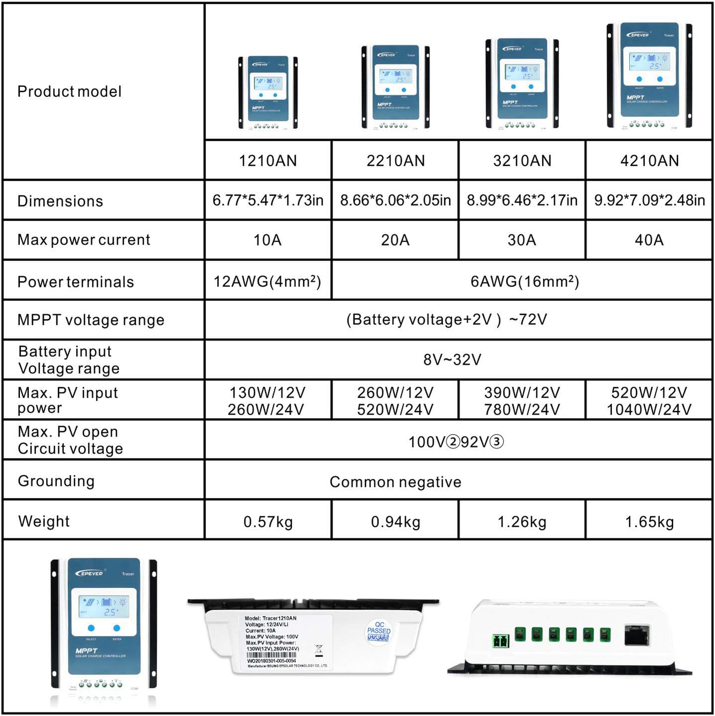
Figure 7: Visual representation of the EPEVER Tracer AN series model comparison table, detailing specifications for 10A, 20A, 30A, and 40A controllers.
6. Accessories (Optional)
Enhance the functionality and monitoring capabilities of your EPEVER controller with these optional accessories:
- Remote Temperature Sensor (RTS300R47K3.81A): For accurate battery temperature compensation, ensuring optimal charging.
- USB to RS485 Cable (CC-USB-RS485-150U): Connects the controller to a PC for monitoring and parameter setting via Solar Station PC software.
- Remote Meter (MT50): Provides real-time data display and allows for convenient parameter adjustments directly from the meter.
- WiFi Serial Adapter (eBox-WIFI-01): Enables wireless monitoring and control via mobile APP.
- RS485 to Bluetooth Adapter (eBox-BLE-01): Allows Bluetooth connectivity for mobile APP monitoring.
- Logger (eLOG01): Records operating data for historical analysis.
- PT Adapter (PT-ADP): Manages communication with multiple controllers in parallel.
7. Troubleshooting
This section provides general guidance for common issues. For complex problems, please contact customer support.
- No Display/Power: Check battery connections and voltage. Ensure battery is charged.
- No Charging: Verify solar panel connections and ensure sufficient sunlight. Check PV voltage.
- Load Not Working: Check load connections, ensure load is within controller's current limits. Verify load working mode settings.
- Battery Over-discharging: Adjust load working mode or increase solar panel capacity. Check battery health.
8. Maintenance
Regular maintenance ensures the longevity and optimal performance of your solar charge controller.
- Clean Terminals: Periodically inspect and clean all terminals to ensure good electrical contact and prevent corrosion.
- Dust Removal: Keep the controller free from dust and debris to ensure proper heat dissipation.
- Cable Inspection: Check all cables for signs of wear, damage, or loose connections.
- Environmental Conditions: Ensure the controller is installed in a well-ventilated area, away from direct sunlight, moisture, and corrosive gases.
9. Warranty and Support
For warranty information, technical support, or service inquiries, please contact EPEVER customer service or your authorized dealer. Keep your purchase receipt for warranty claims.
Manufacturer: EPEVER
Related documentsTracer1206


Ask a question about this manual
Ask about setup, troubleshooting, compatibility, parts, safety, or missing instructions. Manuals+ will review the question and use this page’s manual context to help answer it.