
AUTOOL BT280
AUTOOL BT280 Electric System Circuit Tester User Manual
Model: BT280
1. Introduction
The AUTOOL BT280 Electric System Circuit Tester is a versatile diagnostic tool designed for automotive electrical systems. It provides comprehensive testing capabilities including multimeter functions, oscilloscope mode, relay testing, injector testing, and component activation. This manual provides detailed instructions for the safe and effective use of your BT280 tester.
2. Safety Information
Always observe the following safety precautions to prevent personal injury or damage to the vehicle and the tester:
- Wear appropriate eye protection.
- Do not use the tester if the cable is damaged.
- Do not connect the tester to voltages exceeding 30V DC.
- Avoid contact with hot engine parts or moving components.
- Ensure the vehicle's ignition is off before connecting or disconnecting the tester, unless specific test procedures require otherwise.
- Keep the tester clean and dry.
3. Package Contents
Verify that all items listed below are included in your package:
- 1 Set BT280 Electric System Circuit Tester
- User Manual (this document)
- Power connection cable with alligator clips
- Auxiliary ground lead
- Probe tip

Image 3.1: Contents of the AUTOOL BT280 package, including the main unit, cables, and accessories.
4. Device Overview
Familiarize yourself with the components of the BT280 tester:

Image 4.1: Diagram illustrating the various parts of the BT280 tester, including the probe tip, LCD screen, function buttons, power connector, and test clamps.
- Probe Tip: Used to contact circuits for testing.
- Front LED Light: Illuminates the work area.
- LCD Screen: Displays test results and menu options.
- Red/Green LED Indicator: Provides visual feedback on polarity (Red for positive, Green for negative).
- Function Buttons: Navigate menus and select functions (Up, Down, Left, Right, OK).
- Hook: For hanging the device during use.
- Auxiliary Ground Lead: Provides an additional ground connection.
- Speaker: Emits audible alerts.
- USB Port: For potential firmware updates or data transfer (refer to manufacturer for specific functionality).
- Power Connector: Connects to the vehicle's power source.
- Cable: Main connection cable.
- Test Clamps: Red for positive (+), Black for negative (-) connection to the vehicle battery.
- Relay Test Port: Dedicated port for relay testing.
5. Initial Setup
- Connect Power: Connect the red test clamp to the vehicle's positive (+) battery terminal and the black test clamp to the vehicle's negative (-) battery terminal. The device will power on automatically.
- Language Selection: Upon first use, or after a reset, you may be prompted to select your preferred language. Use the navigation buttons to select and press OK. The BT280 supports 14 languages including English, Spanish, German, Russian, Italian, Polish, Portuguese, French, Vietnamese, Malaysian, Filipino, Indonesian, Arabic, and Thai.
- Probe Tip Attachment: Ensure the probe tip is securely attached to the main unit.
6. Operating Modes
The BT280 offers several operating modes accessible from the main menu. Use the navigation buttons to select a mode and press OK.

Image 6.1: The main interface of the BT280 showing icons for Smart Test, Multimeter, Oscilloscope, Relay, Active, Powered by, Injector, P-N, and Setup functions.
6.1 Smart Test Mode
This mode automatically identifies voltage, resistance, and polarity (positive/negative) of the tested component. Simply touch the probe tip to the circuit or component. The screen will display the detected values and polarity.

Image 6.2: Examples of Smart Test results, showing automatic identification of positive voltage, negative voltage, and resistance values.
6.2 Multimeter Mode
The Multimeter Mode provides comprehensive measurements including DC voltage, resistance, diode/continuity, current, and frequency. Use the navigation buttons to select the desired measurement type.

Image 6.3: The Multimeter Mode interface displaying various electrical parameters such as DC voltage, resistance, diode/continuity, current, and frequency. The device also features a flashlight for illuminating dark areas.
6.3 Oscilloscope Mode
This mode displays the parameter curve diagram of the tested component, such as voltage, frequency, and time. This is useful for analyzing signal waveforms.

Image 6.4: The Oscilloscope Mode interface displaying a waveform. The 'DIV' setting allows adjustment of voltage per grid (test range 1V-49V) by pressing the up and down keys.
6.4 Component Activation
The BT280 can generate 'Active' signals to test components like lights, motors, and other on-board electronic devices. This allows for functional testing of components outside of their normal operating circuit.
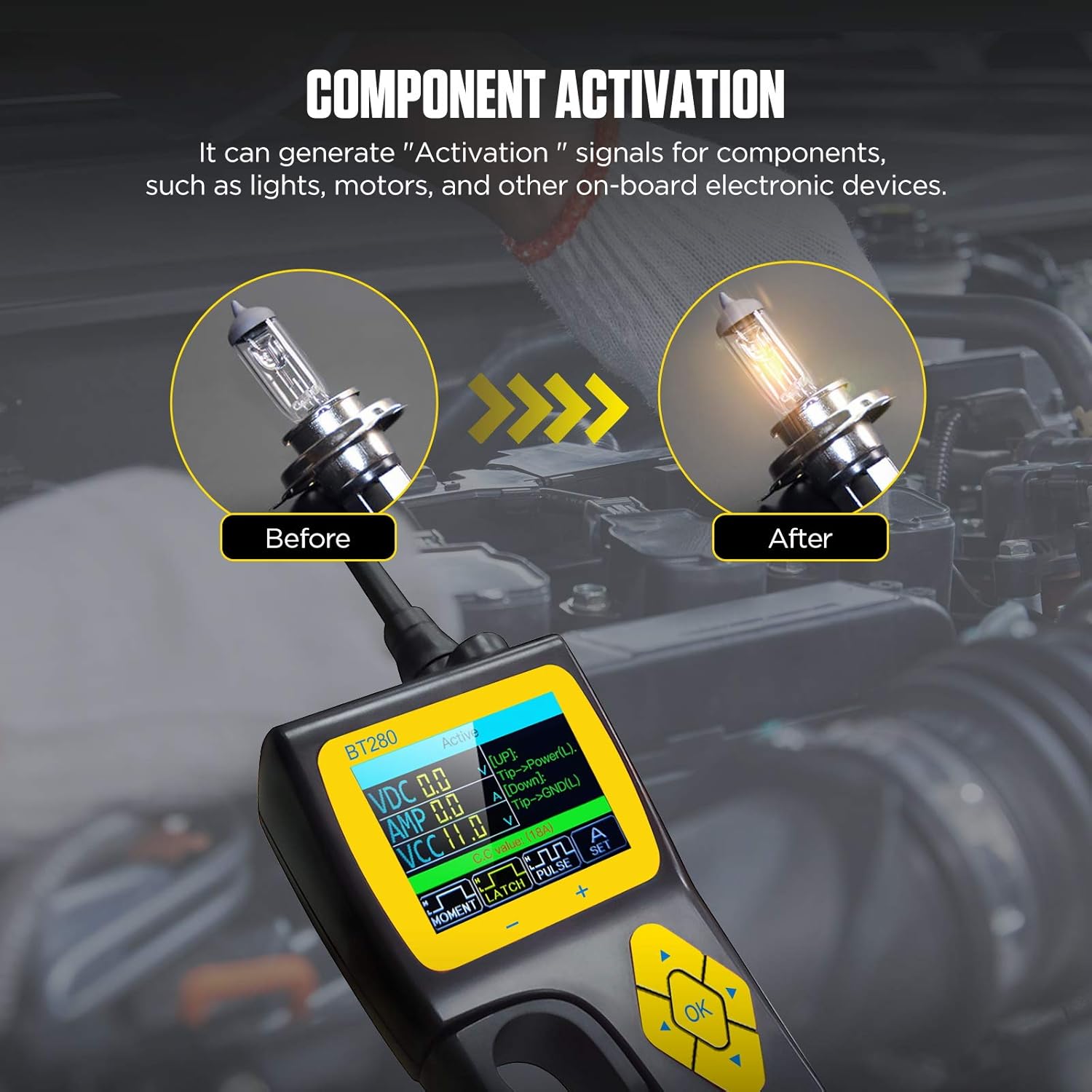
Image 6.5: The Component Activation function being used to test a light bulb, demonstrating its ability to provide power to activate components.
6.5 Relay Test
This mode allows testing of common automotive relays, including 5-terminal and 4-terminal relays. Connect the relay to the dedicated relay test port and follow the on-screen instructions.

Image 6.6: The Relay Test function showing connections for both 5-terminal and 4-terminal automotive relays, along with a schematic diagram.
6.6 Injector Mode
The BT280 can output different pulse signals to an injector, providing 4 pulse modes to detect the injector's condition. This helps in diagnosing fuel injector issues.
6.7 0-5V Power Supply
This function allows you to set an output voltage between 0-5V, useful for verifying the wiring condition of a tested component or powering small circuits.
6.8 Voltage Alarm
The device is equipped with a voltage setting alarm. If a short circuit or fault causes the voltage to be greater than or less than a user-defined set value, the device will emit an alarm.
7. Maintenance
7.1 Care and Cleaning
- Clean the tester's exterior with a soft, damp cloth. Do not use abrasive cleaners or solvents.
- Keep the probe tip clean and free of debris.
- Ensure all connections are clean and dry before use.
7.2 Storage
- Store the BT280 in its original case or a suitable protective container when not in use.
- Store in a cool, dry place, away from direct sunlight and extreme temperatures.
8. Troubleshooting
This section addresses common issues you might encounter with your BT280 tester.
| Problem | Possible Cause | Solution |
|---|---|---|
| Tester does not power on. | Incorrect battery connection; Vehicle battery discharged. | Ensure red clamp is on positive (+), black on negative (-). Check vehicle battery voltage. |
| Inaccurate readings. | Poor connection; Damaged probe tip or cable; Incorrect mode selected. | Ensure secure connections. Inspect probe and cable for damage. Select the appropriate testing mode. |
| Screen is blank or frozen. | Software glitch; Power interruption. | Disconnect and reconnect power. If issue persists, contact customer support. |
| No sound from speaker. | Volume muted; Speaker malfunction. | Check device settings for volume. If still no sound, contact customer support. |
9. Technical Specifications
| Specification | Value |
|---|---|
| Operating Voltage | 9V-30V DC |
| Display | 2.4-inch LCD |
| Item Model Number | BT280 |
| Package Dimensions | 11.93 x 10.39 x 4.41 inches |
| Item Weight | 1.68 Kilograms (3.7 Pounds) |
| Power Source | Battery Powered (via vehicle battery) |
| Supported Languages | 14 (English, Spanish, German, Russian, Italian, Polish, Portuguese, French, Vietnamese, Malaysian, Filipino, Indonesian, Arabic, Thai) |
10. Warranty and Support
10.1 Warranty Information
The AUTOOL BT280 Electric System Circuit Tester comes with a Three Years Warranty for damage caused by non-human factors. AUTOOL promises to resend parts for free within this period. Additionally, the product includes Lifetime Maintenance.
10.2 Customer Support
For any technical assistance, warranty claims, or inquiries, please contact AUTOOL customer support. You are welcomed to contact us, and we will respond within 24 hours.
Please refer to the AUTOOL official website or your purchase documentation for the most current contact information.
Related documentsBT280


Ask a question about this manual
Ask about setup, troubleshooting, compatibility, parts, safety, or missing instructions. Manuals+ will review the question and use this page’s manual context to help answer it.