
Introduction
This manual provides essential instructions for the assembly, operation, and maintenance of your Aitoserlea Aluminum Metal 6DOF 6 Axis Robot Arm. Please read this manual thoroughly before beginning assembly or operation to ensure proper use and to maximize the lifespan of your robot arm.
Product Overview
The Aitoserlea 6DOF Robot Arm is an all-metal manipulator designed for educational and functional applications. It features six degrees of freedom, allowing for complex movements and precise positioning.
Key Features:
- 6 Degrees of Freedom (DOF) for versatile movement.
- All-metal construction for durability and stability.
- Equipped with 4 MG996R metal gear servos and 2 MG90S metal gear servos for powerful and precise control.
Components Included:
The kit includes all necessary components for assembly, such as aluminum alloy structural parts, 4 MG996R servos, 2 MG90S servos, and various fasteners. An Arduino board or similar controller is not included and must be acquired separately for operation.
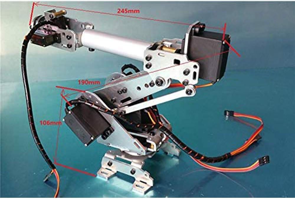
Figure 1: Assembled Aitoserlea 6DOF Robot Arm. This image displays the robot arm from a general perspective, highlighting its metallic structure and the placement of the servo motors.
Setup and Assembly
The robot arm is provided as a kit and requires assembly. While detailed step-by-step instructions are typically provided by the seller via PDF, the general assembly process involves attaching the aluminum components and integrating the servo motors.
- Unpack Components: Carefully unpack all parts and verify against the included parts list (if provided). Ensure all fasteners and servos are present.
- Structural Assembly: Begin by assembling the base and primary arm segments using the provided aluminum brackets and fasteners. Pay close attention to the orientation of each piece.
- Servo Installation: Install the MG996R and MG90S servos into their designated positions. Ensure the servo horns are correctly aligned before securing them. The MG996R servos are typically used for the more powerful joints (e.g., base rotation, main arm lift), while MG90S servos are for lighter joints (e.g., wrist, gripper if applicable).
- Wiring: Connect the servo wires to your chosen control board (e.g., Arduino). It is recommended to manage wires using electrical tape or cable ties to prevent interference with arm movement.
- Initial Testing: Before full operation, perform basic tests to ensure all joints move freely and servos respond correctly to control signals. Adjust any 4-point joints as needed to achieve the desired range of motion. The base joint typically offers about 270 degrees of rotation, while other joints provide approximately 180 degrees.
- Mounting: For stable operation, it is highly recommended to mount the robot arm to a sturdy base or board. This prevents tipping during larger movements.

Figure 2: Robot Arm Dimensions. This image illustrates the approximate dimensions of the robot arm, including arm segment lengths and overall height, which are crucial for planning its integration and workspace.
Operating Instructions
The Aitoserlea 6DOF Robot Arm requires an external microcontroller (e.g., Arduino, Raspberry Pi) and programming to function. This section provides general guidance on operation.
- Controller Connection: Connect the servo control wires to the appropriate digital or PWM pins on your microcontroller. Ensure the power supply for the servos is adequate and separate from the microcontroller's logic power if necessary.
- Programming: Develop or load control code onto your microcontroller. This code will translate desired movements into servo commands (e.g., pulse width modulation signals).
- Calibration: Calibrate each servo to ensure its full range of motion is utilized and that its neutral position is correctly set. This is critical for accurate and repeatable movements.
- Movement Control:
- Base Rotation: Controls the horizontal movement of the entire arm.
- Shoulder Joint: Controls the vertical movement of the main arm segment.
- Elbow Joint: Controls the bending of the arm's middle segment.
- Wrist Joints (2 DOF): Provide pitch and roll movements for the end effector.
- End Effector (1 DOF): Controls the gripper or tool attached to the arm (if applicable, not included).
- Safety: Always operate the robot arm in a clear workspace. Keep hands and loose clothing away from moving parts. Disconnect power when making adjustments or performing maintenance.
Maintenance
Regular maintenance ensures the longevity and optimal performance of your robot arm.
- Cleanliness: Keep the robot arm free from dust and debris. Use a soft, dry cloth for cleaning. Avoid using liquids directly on electronic components.
- Fastener Check: Periodically inspect all screws and bolts for tightness. Vibrations during operation can loosen fasteners over time.
- Servo Inspection: Check servo motors for any signs of wear, unusual noise, or reduced performance. Replace damaged servos promptly.
- Wire Management: Ensure all wires are securely routed and not pinched or stressed. Re-secure any loose wiring.
- Lubrication: Moving joints and gears may benefit from light lubrication with a suitable plastic-safe lubricant, if recommended by the servo manufacturer.
Troubleshooting
| Problem | Possible Cause | Solution |
|---|---|---|
| Arm does not move or moves erratically. |
|
|
| Arm tips over during movement. |
|
|
| Joints have excessive slack or play. |
|
|
Specifications
| Feature | Detail |
|---|---|
| Brand | Aitoserlea |
| Model Number | RA21-0127-0001 |
| Degrees of Freedom (DOF) | 6 |
| Material | Aluminum Alloy |
| Servos Included | 4 x MG996R, 2 x MG90S |
| Item Weight | 840 Grams |
| Educational Objective | STEM, Robotics |
| UPC | 755205953230 |
Warranty Information
Specific warranty details for the Aitoserlea Aluminum Metal 6DOF 6 Axis Robot Arm are not provided in the available product information. Please refer to the seller's or manufacturer's website for current warranty terms and conditions, or contact their customer service directly.
Support
For technical assistance, assembly instructions (PDF), or troubleshooting beyond this manual, please contact the Aitoserlea customer support. Contact information may be found on the product packaging or the seller's online store page.
Note: The top review mentions that assembly instructions were provided by the seller via email as a PDF upon request.