
1. Introduction
The RICHMETERS RM098 is a professional auto-ranging digital multimeter designed for accurate measurement of various electrical parameters. It is an ideal tool for laboratories, factories, electronics enthusiasts, and general household use. This manual provides essential information for safe and effective operation of your device.
2. Safety Information
To ensure safe operation and avoid damage to the meter, please read and follow all safety instructions carefully.
- Maximum Input Voltage: Do not apply more than 600V DC between the test leads and ground. Exceeding this limit can cause electric shock or damage to the device.
- Fuse Protection: The meter is protected by a 0.2A / 250V fast-blow ceramic fuse for current measurements. Ensure the correct fuse type is used for replacement.
- Battery Installation: Always ensure batteries are correctly installed according to polarity markings. Remove batteries if the meter is not used for an extended period.
- Inspection: Before each use, inspect the meter and test leads for any damage. Do not use if damaged.
- Operating Environment: Use the meter within the specified operating temperature and humidity ranges (0-20°C, <70% RH).
3. Package Contents
Verify that all items listed below are included in your package:
- 1 x RICHMETERS RM098 Digital Multimeter
- 1 x Pair of Test Leads (Red and Black)
- 1 x English User Manual
- 1 x Carrying Bag
4. Product Features and Components
Familiarize yourself with the main components of the RM098 Digital Multimeter.
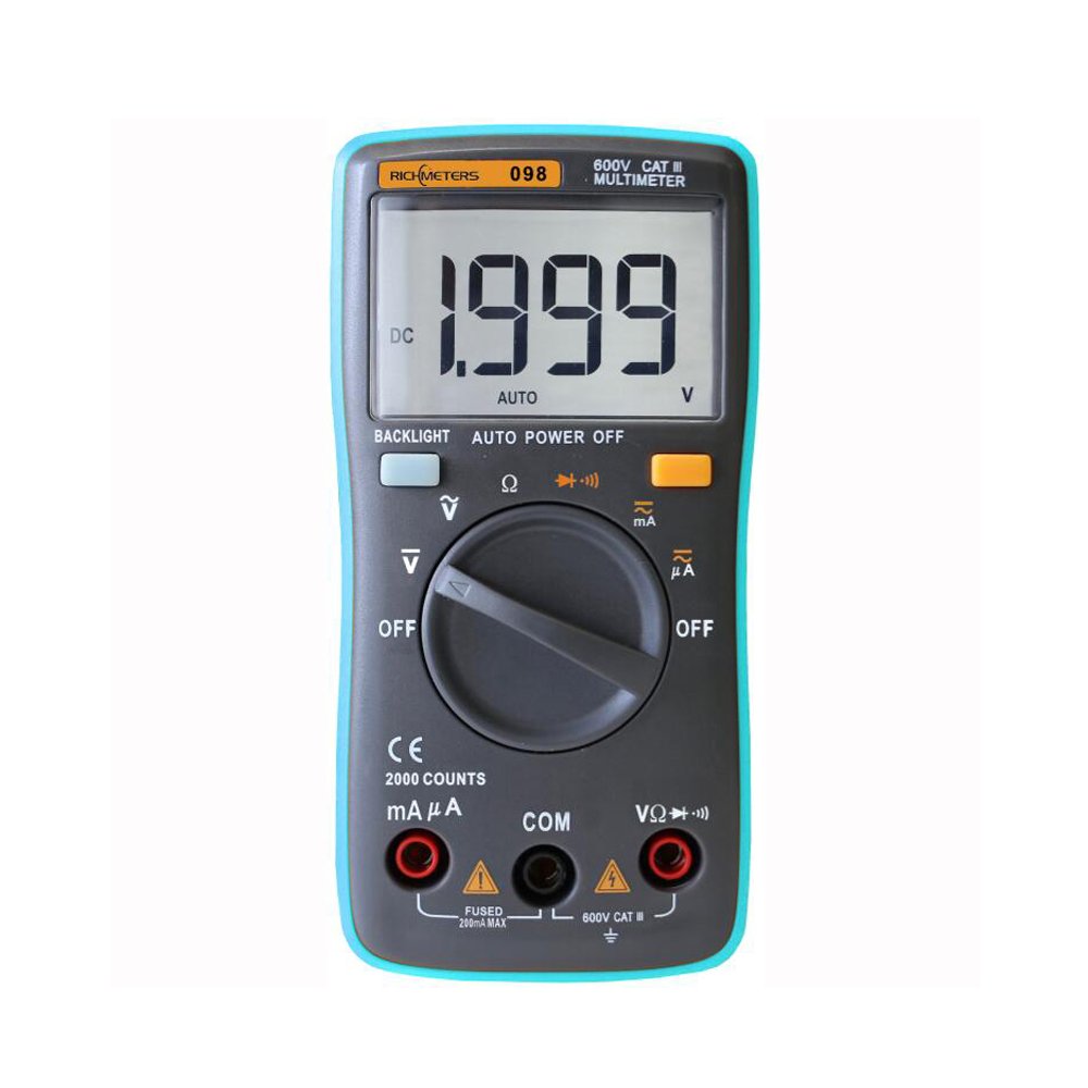
Figure 1: Front view of the RICHMETERS RM098 Digital Multimeter, showing the LCD screen, rotary function switch, and input terminals.

Figure 2: The multimeter with its red and black test leads properly connected to the input jacks.

Figure 3: Detailed view of the test leads, showing the probe tips and insulated handles.

Figure 4: Side profile of the multimeter, highlighting its compact design.
Key Components:
- LCD Display: Shows measurement readings, units, and function indicators.
- Function Rotary Switch: Used to select measurement functions (Voltage, Current, Resistance, Diode, Continuity).
- Input Jacks:
- COM Jack (Black): Common terminal for all measurements.
- VΩmA Jack (Red): Input for Voltage, Resistance, Diode, Continuity, and milliampere/microampere current measurements.
- 10A Jack (Red): Input for 10 Ampere current measurements (if applicable, this model has 200mA max). Note: This model's current ranges are up to 200mA, so the 10A jack is not used.
- Backlight Button: Activates the display backlight.
- Hold Button: Freezes the current reading on the display.
5. Setup
5.1. Battery Installation
- Ensure the multimeter is turned OFF.
- Locate the battery compartment cover on the back of the meter.
- Use a screwdriver to remove the screws securing the battery cover.
- Insert two 1.5V AAA batteries, observing the correct polarity (+ and -) as indicated inside the compartment.
- Replace the battery cover and secure it with the screws.

Figure 5: Rear view of the multimeter, indicating the battery compartment.
5.2. Connecting Test Leads
- Insert the black test lead into the COM (Common) jack.
- For most measurements (Voltage, Resistance, Diode, Continuity, and current up to 200mA), insert the red test lead into the VΩmA jack.
- Ensure the connections are firm before taking any measurements.
6. Operating Instructions
The RM098 features auto-ranging, simplifying operation by automatically selecting the correct measurement range.
6.1. Power On/Off
Turn the rotary switch from the 'OFF' position to any desired measurement function to power on the meter. To power off, turn the rotary switch back to 'OFF'. The meter also features an auto power-off function to conserve battery life.
6.2. Measuring DC Voltage (V–)
- Set the rotary switch to the 'V–' position.
- Connect the red test lead to the positive (+) side of the circuit and the black test lead to the negative (-) side.
- Read the voltage value on the LCD display. The meter will automatically detect polarity.
6.3. Measuring AC Voltage (V∼)
- Set the rotary switch to the 'V∼' position.
- Connect the test leads across the AC voltage source.
- Read the voltage value on the LCD display.
6.4. Measuring DC Current (mA– / µA–)
- IMPORTANT: To measure current, the meter must be connected in series with the circuit. Disconnect power to the circuit before connecting the meter.
- Set the rotary switch to the 'mA–' or 'µA–' position, depending on the expected current range.
- Break the circuit and connect the meter in series. The red lead connects to the higher potential side, and the black lead to the lower potential side.
- Apply power to the circuit and read the current value on the LCD display.
6.5. Measuring AC Current (mA∼ / µA∼)
- IMPORTANT: To measure current, the meter must be connected in series with the circuit. Disconnect power to the circuit before connecting the meter.
- Set the rotary switch to the 'mA∼' or 'µA∼' position, depending on the expected current range.
- Break the circuit and connect the meter in series.
- Apply power to the circuit and read the current value on the LCD display.
6.6. Measuring Resistance (Ω)
- Set the rotary switch to the 'Ω' position.
- Ensure the circuit or component under test is completely de-energized before measuring resistance.
- Connect the test leads across the component or circuit where resistance is to be measured.
- Read the resistance value on the LCD display.
6.7. Diode Test (→|)
- Set the rotary switch to the '→|' position.
- Connect the red test lead to the anode of the diode and the black test lead to the cathode.
- The display will show the forward voltage drop. Reverse the leads; the display should show 'OL' (Open Loop) for a good diode.
6.8. Continuity Test (♫)
- Set the rotary switch to the '♫' position.
- Connect the test leads across the circuit or component.
- If the resistance is below approximately 60Ω, the buzzer will sound, indicating continuity. The display will also show the resistance value.
7. Specifications
Detailed technical specifications for the RICHMETERS RM098 Digital Multimeter.

Figure 6: Comprehensive specifications table for the RM098, including measurement ranges, accuracy, and resolution.
| Feature | Specification |
|---|---|
| Model | RM098 |
| Display | 2000 Counts |
| Sampling Rate | Approx. 3 times/second |
| Input Impedance | 10 MΩ (for voltage ranges) |
| Diode Test Current | 1.0 ± 0.7 mA |
| Continuity Audible Indicator | Less than 60 Ω |
| Operating Temperature | 0-20°C, <70% RH |
| Storage Temperature | -20-60°C, <80% RH (with battery removed) |
| Max. Input Protection | 0.2A / 250V Fast Blow Ceramic Fuse (for current) |
| Power Supply | 2 x 1.5V AAA Batteries (not included) |
| Item Weight | 112 g / 3.94 oz |
| Product Size | 12.5 x 6.5 x 3 cm / 4.9 x 2.56 x 1.18 inches |
Measurement Specifications:
| Function | Range | Accuracy | Resolution |
|---|---|---|---|
| DC Voltage | 200.0mV | ±0.8%+5 | 0.1mV |
| 2.000V | ±0.5%+5 | 1mV | |
| 20.00V | ±0.5%+5 | 10mV | |
| 200.0V | ±0.8%+5 | 0.1V | |
| 800.0V | ±1%+8 | 1V | |
| AC Voltage | 200.0mV | ±1.5%+5 | 0.1mV |
| 2.000V | ±1.2%+5 | 1mV | |
| 20.00V | ±1.2%+5 | 10mV | |
| 200.0V | ±1.5%+5 | 0.1V | |
| 600.0V | ±1.5%+5 | 1V | |
| DC Current | 200.0µA | ±1.5%+5 | 0.1µA |
| 2000µA | ±1.2%+5 | 1µA | |
| 20.00mA | ±1.2%+5 | 0.01mA | |
| 200.0mA | ±1.2%+5 | 0.1mA | |
| AC Current | 200.0µA | ±2%+5 | 0.1µA |
| 2000µA | ±1.5%+5 | 1µA | |
| 20.00mA | ±2%+5 | 0.01mA | |
| 200.0mA | ±1.5%+5 | 0.1mA | |
| Resistance | 200.0Ω | ±1%+5 | 0.1Ω |
| 2.000kΩ | ±1%+5 | 1Ω | |
| 20.00kΩ | ±1%+5 | 10Ω | |
| 200.0kΩ | ±1%+5 | 100Ω | |
| 2.000MΩ | ±1%+5 | 1kΩ | |
| 20.00MΩ | ±2.5%+5 | 10kΩ |
8. Maintenance
8.1. Cleaning
Wipe the meter's casing with a damp cloth and mild detergent. Do not use abrasives or solvents. Ensure the meter is dry before use.
8.2. Battery Replacement
When the battery indicator appears on the LCD, replace the batteries as described in the 'Battery Installation' section (5.1). Always use fresh 1.5V AAA batteries.
8.3. Fuse Replacement
If the current measurement function fails, the fuse may need replacement. Refer to the safety information for fuse specifications (0.2A / 250V fast blow ceramic fuse). Fuse replacement should only be performed by qualified personnel.
9. Troubleshooting
If you encounter issues with your RM098 multimeter, refer to the following common problems and solutions:
- Meter does not power on:
- Check if the rotary switch is set to an ON position.
- Verify that the batteries are correctly installed and not depleted. Replace if necessary.
- No reading or 'OL' (Overload) displayed:
- Ensure test leads are properly connected to the meter and the circuit.
- Check if the correct function is selected for the measurement.
- For resistance measurements, ensure the circuit is de-energized.
- If measuring current, check the fuse.
- Inaccurate readings:
- Ensure test leads are making good contact.
- Check battery level; low batteries can affect accuracy.
- Ensure the meter is used within its specified operating conditions.
10. Warranty and Support
Specific warranty information for the RICHMETERS RM098 Digital Multimeter is not provided in this manual. For warranty claims, technical support, or service inquiries, please contact your original point of purchase or the manufacturer directly. Keep your purchase receipt as proof of purchase.

