
1. Introduction
The DROK DC Buck Converter is a compact and efficient voltage regulator module designed to step down a higher DC input voltage to a lower, stable DC output voltage. This module is suitable for a wide range of electronic projects and applications requiring a regulated power supply. Its small size makes it ideal for space-constrained designs.

Figure 1: Overview of DROK DC Buck Converters.
This package includes six individual buck converter modules, each capable of providing either a fixed or adjustable output voltage from a 4.5V-20V input.
2. Safety Information
- Always disconnect power before making any connections or adjustments to the module.
- Ensure correct polarity when connecting input and output wires to prevent damage to the module and connected devices.
- Do not exceed the maximum input voltage (20V) or output current (3A peak, 2A long-term) specifications.
- While the module features output short circuit protection, avoid prolonged short circuits as this can lead to overheating and potential damage.
- Handle the module with care to avoid electrostatic discharge (ESD) damage.
- Keep the module away from moisture, dust, and extreme temperatures.
- Installation and modifications should only be performed by qualified personnel.
3. Product Features
- Wide Input Voltage Range: Accepts DC 4.5V to 20V.
- Versatile Output: Output voltage can be either adjustable (1V-16V) or fixed (1.8V, 2.5V, 3.3V, 5V, 9V, 12V).
- High Current Capability: Supports a maximum output current of 3A (peak) and 2A (long-term).
- Efficient Conversion: Achieves up to 97% conversion efficiency (typically >90% when stepping down 12V to 5V at 2A).
- Output Short Circuit Protection: Integrated protection against output short circuits.
- Enable Control Port: Features an enable (EN) port for external control, allowing the module to be turned off at a low electric level.
- Ultra-Compact Design: Extremely small footprint, making it suitable for integration into various projects.
4. Specifications
| Parameter | Value |
|---|---|
| Input Voltage | DC 4.5V - 20V |
| Output Voltage (Adjustable) | DC 1V - 16V |
| Output Voltage (Fixed Options) | 1.8V, 2.5V, 3.3V, 5V, 9V, 12V |
| Output Current (Max) | 3A (Peak) |
| Output Current (Long-term) | Within 2A |
| Output Power | 10W |
| Conversion Efficiency | Up to 97% (Typical >90% for 12V to 5V @ 2A) |
| Dimensions (L x W) | 19.5mm x 14mm (approx. 0.77 x 0.55 inches) |
| Item Weight | Approx. 1.13 ounces (for the pack of 6) |

Figure 2: Module Dimensions.

Figure 3: Size comparison of the module.
5. Setup and Configuration
5.1 Pin Identification
The module has clearly labeled input and output pads for easy connection. Refer to the diagram below:
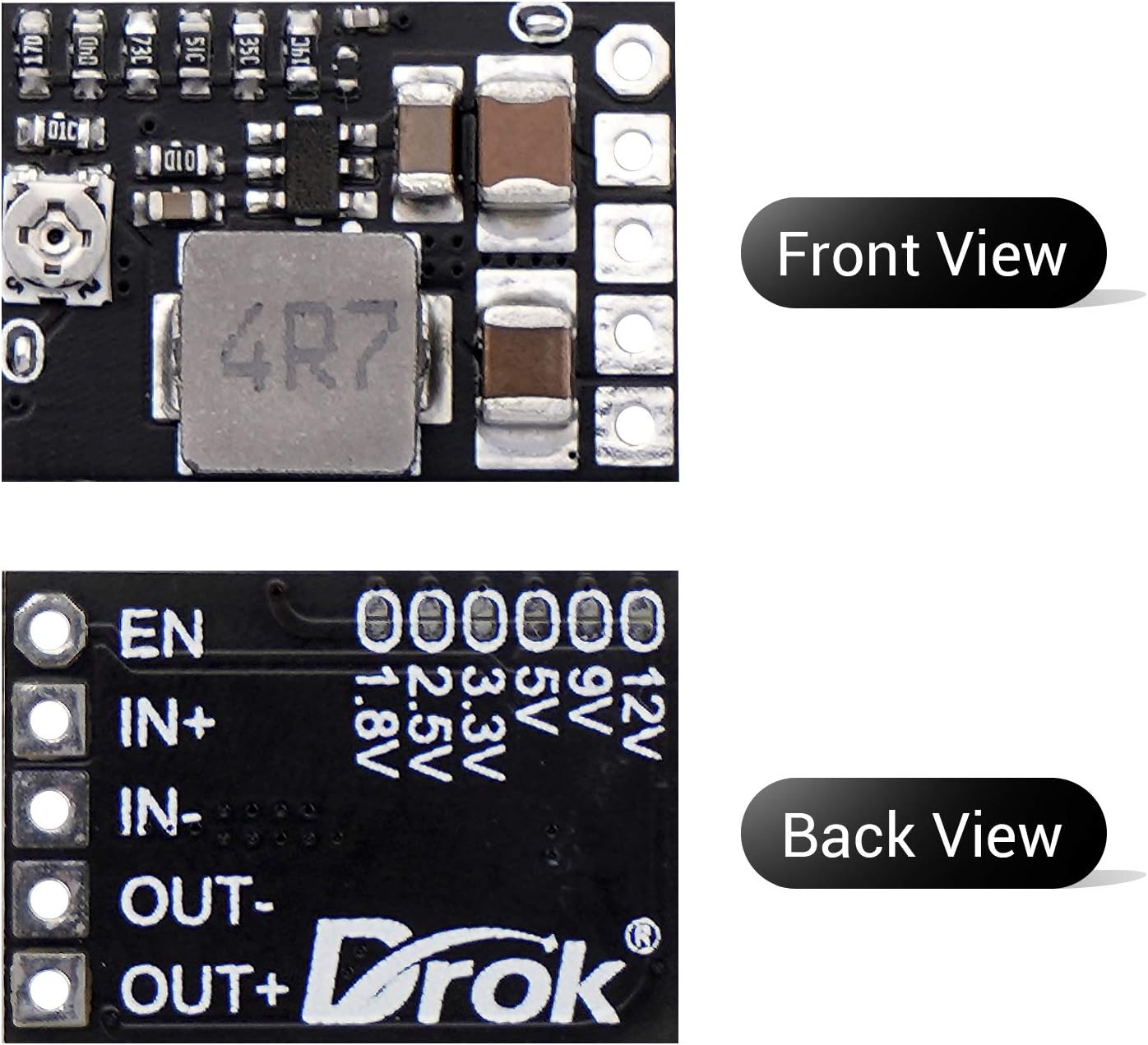
Figure 4: Front and Back View with Pin Labels.
- EN: Enable Port (for external control)
- IN+: Positive Input Voltage
- IN-: Negative Input Voltage (Ground)
- OUT-: Negative Output Voltage (Ground)
- OUT+: Positive Output Voltage
5.2 Output Voltage Configuration (Adjustable vs. Fixed)
The module defaults to adjustable output voltage. To switch to a fixed output voltage, a modification is required on Pad A.

Figure 5: Configuration Pads and Trimmer Potentiometer.
- Adjustable Output (Default): The small board is configured by default for output voltage adjustment using the onboard trimmer potentiometer. No action is needed for this mode.
- Fixed Output:
- Locate Pad A on the module (refer to Figure 5). This pad is welded together by default.
- Carefully cut the trace in the middle of Pad A using a sharp tool (e.g., a hobby knife). This disconnects the adjustable potentiometer.
- On the back side of the module, locate the pads for the desired fixed voltage (1.8V, 2.5V, 3.3V, 5V, 9V, 12V).
- Solder together the two halves of the pad corresponding to your desired fixed voltage. For example, to set 5V output, solder the 5V pad.
5.3 Enable Port Control
The enable (EN) port is welded together by default, meaning the module is always in working mode. To enable external control of the module's on/off state:
- Locate Pad B (Enable port control pad) on the module (refer to Figure 5).
- Carefully cut the trace in the middle of Pad B using a sharp tool.
- Once Pad B is cut, the module will turn off when a low electric level (e.g., ground) is applied to the EN pin. It will operate when the EN pin is left floating or connected to a high logic level.
6. Operating Instructions
- Connect Input Power: Connect your DC power source (4.5V-20V) to the IN+ and IN- pads, ensuring correct polarity.
- Set Output Voltage (Adjustable Mode): If you have configured the module for adjustable output, use a small screwdriver to carefully turn the trimmer potentiometer (refer to Figure 5) to achieve your desired output voltage.
- Verify Output Voltage: Crucially, always measure the output voltage with a multimeter before connecting any load to ensure it matches your requirements and prevent damage to your devices.
- Connect Load: Once the output voltage is verified, connect your load to the OUT+ and OUT- pads, observing polarity.
- Using Enable Pin (if configured): If you have cut Pad B, you can control the module's operation by applying a low signal (e.g., ground) to the EN pin to turn it off, and releasing it or applying a high signal to turn it on.
7. Maintenance
- Keep the module clean and free from dust and debris.
- Store in a dry environment, away from direct sunlight and extreme temperatures.
- Regularly inspect connections for any signs of wear or corrosion.
8. Troubleshooting
| Problem | Possible Cause | Solution |
|---|---|---|
| No output voltage. | No input power, incorrect wiring, enable pin low (if configured). | Check input power supply. Verify IN+ and IN- connections. If EN pin is used, ensure it's not held low. |
| Output voltage is incorrect/unstable. | Potentiometer not adjusted correctly (adjustable mode), incorrect fixed voltage pad soldered, faulty module. | Adjust the trimmer potentiometer. Verify fixed voltage pad soldering. Test with a known good input/load. |
| Module overheats. | Output current exceeds maximum rating, prolonged short circuit. | Reduce load current to stay within 2A long-term. Ensure no short circuits. Consider heat sinking for continuous high-current operation. |
| Module stopped working after a short circuit. | Prolonged short circuit, protection circuit tripped. | Remove the short circuit. Disconnect and reconnect input power to reset the module. Avoid prolonged short circuits. |
9. Warranty and Support
DROK products are designed for reliability and performance. For any quality issues or technical assistance, please contact DROK customer support. Your satisfaction is important to us. We offer a one-year service period for products purchased from DROK, including replacement for quality-related issues.
For further information or to contact support, please visit the official DROK store or contact your retailer.
Official DROK Store: https://www.amazon.com/stores/DROK/page/AEB10E82-8554-4FC1-BBD0-354046DAE77C


