
Introduction
This manual provides detailed instructions for the safe and effective operation of the AOPUTTRIVER AP-7200APP Professional True-RMS Clamp Meter. This device is designed for measuring AC/DC current, AC/DC voltage, resistance, capacitance, continuity, and temperature, and features non-contact voltage (NCV) detection and Bluetooth connectivity for mobile app integration.
Safety Information
Always adhere to safety precautions when using electrical testing equipment. This device complies with IEC 61010-1, CAT III 600V safety standards and features double insulation for enhanced protection.
- Do not exceed the maximum input values specified for each measurement range.
- Exercise extreme caution when working with live circuits.
- Ensure the test leads are in good condition and properly connected before use.
- Do not operate the meter if it appears damaged or if the casing is open.
- Refer to local and national safety codes for proper electrical work procedures.
Package Contents
Verify that all items listed below are included in your package:
- AOPUTTRIVER AP-7200APP Clamp Meter
- Temperature Probe
- Test Leads (Red/Black)
- Batteries (AAA type, typically 2)
- Instruction Manual

Image: Contents of the AP-7200APP package, including the clamp meter, temperature probe, test leads, batteries, and instruction manual.
Product Overview
Familiarize yourself with the components of the AP-7200APP Clamp Meter:

Image: Labeled diagram of the AP-7200APP Clamp Meter, highlighting its main components and controls.
- Clamp Jaws: Opens 26mm to enclose conductors for current measurement.
- Jaw-opening Handle: Used to open and close the clamp jaws.
- NCV Detection Area: Located at the top, used for non-contact voltage detection.
- Lamp Light: Illuminates the measurement area. Press the "HOLD" key for over 2 seconds to activate.
- Rotary Switch: Selects measurement functions and ranges.
- LCD Display: 6000 counts display, showing measurement values and function symbols.
- HOLD Key: Freezes the current display reading. Press for >2 seconds to activate backlight.
- SEL Key: Used to change measurement modes within a function (e.g., AC/DC, Diode/Continuity/Capacitance).
- MAX/MIN Key: Records maximum and minimum measured values. Press for >2 seconds to exit.
- Hz/Duty Key: Selects frequency or duty cycle measurement.
- REL Key: Activates relative measurement mode.
- COM Input Jack: Common terminal for test leads and temperature probe.
- VΩHz°C°F Input Jack: Input terminal for voltage, resistance, frequency, capacitance, and temperature measurements.
Setup
1. Battery Installation
The meter requires two AAA batteries. Open the battery compartment cover on the back of the device, insert the batteries according to the polarity indicators, and securely close the cover. A low battery indicator will appear on the LCD when replacement is needed.
2. Bluetooth Connection (AiLink App)
The AP-7200APP can connect to a mobile device via Bluetooth for remote monitoring and data analysis. The effective control distance is approximately 10-15 meters.
- Download the App: Scan the QR code provided in the manual or search for "AiLink" in the Google Play Store (for Android) or Apple App Store (for iOS). Download and install the application. You can also download it from aicare.net.cn/app/ailink/download/.
- Open the App: Launch the AiLink application on your mobile phone.
- Connect to Device: Within the app, press the "ADD" or "Connect" button to search for nearby devices. Select the "Clamp Meter" from the list to establish a connection.
- Monitor Data: Once connected, the app will display real-time measurement data from the clamp meter. You can analyze and save this data.

Image: Visual guide for Bluetooth connection and app usage, showing the AiLink app interface.
Operating Instructions
Before any measurement, ensure the rotary switch is set to the OFF position when not in use.
1. AC/DC Current Measurement (Clamp)
- Set the rotary switch to the 60A~ or 400A~ position for AC current, or 60A= or 400A= for DC current.
- Press the jaw-opening handle to open the clamp jaws.
- Enclose a single conductor with the clamp jaws. Ensure the conductor is centered within the jaws for accurate readings.
- Read the current value on the LCD display.
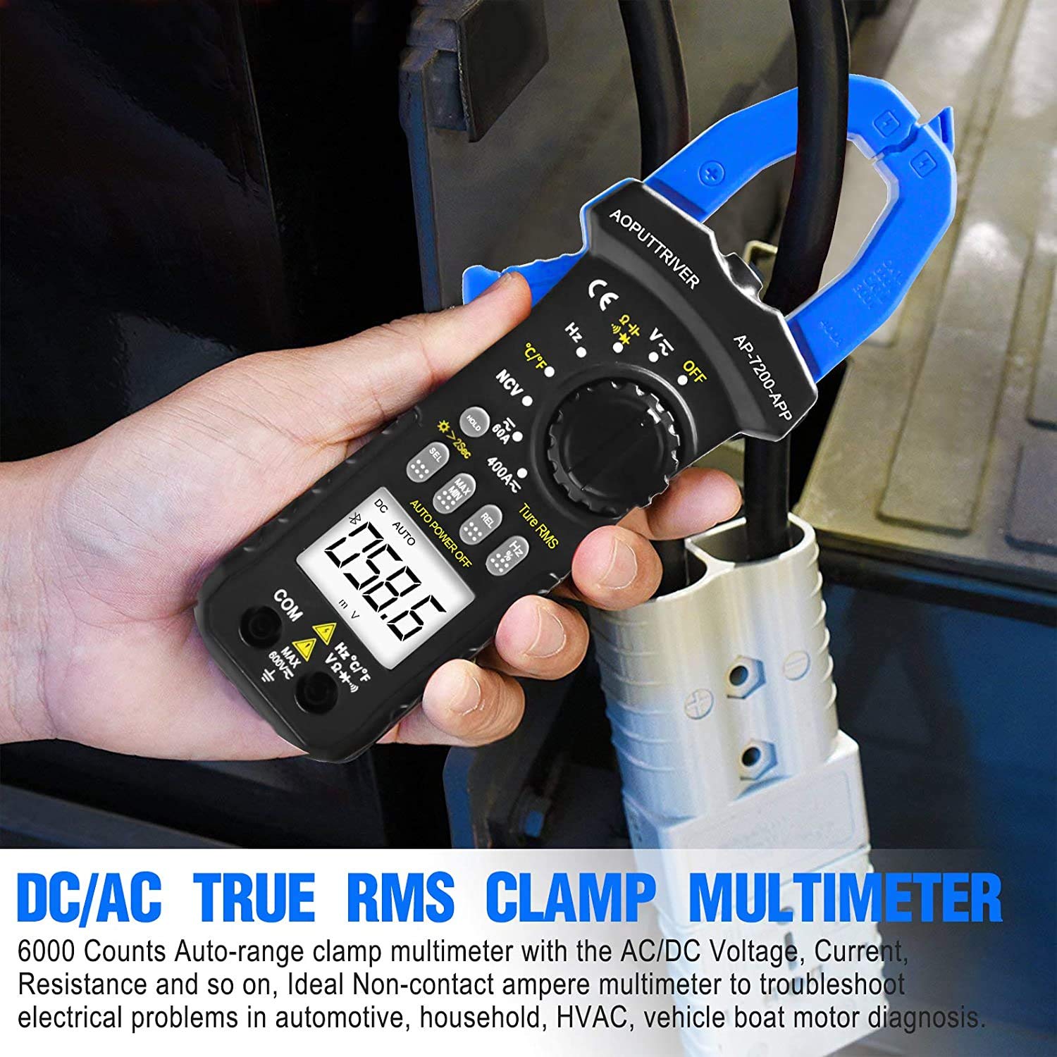
Image: Demonstrating current measurement using the clamp jaws on an electrical cable.
2. AC/DC Voltage Measurement
- Insert the red test lead into the VΩHz°C°F jack and the black test lead into the COM jack.
- Set the rotary switch to the V~ (AC Voltage) or V= (DC Voltage) position.
- Connect the test leads in parallel to the circuit or component under test.
- Read the voltage value on the LCD display.
3. Resistance, Capacitance, Continuity, Diode Measurement
- Insert the red test lead into the VΩHz°C°F jack and the black test lead into the COM jack.
- Set the rotary switch to the Ω position.
- Press the SEL key to cycle through Resistance (Ω), Continuity (buzzer icon), Diode (diode icon), and Capacitance (F) modes.
- Connect the test leads to the component. For resistance and capacitance, ensure the component is de-energized.
- Read the measurement on the LCD. For continuity, a beep indicates a continuous circuit.
4. Non-Contact Voltage (NCV) Detection
- Set the rotary switch to the NCV position.
- Place the NCV detection area (top of the clamp jaws) near the conductor or outlet to be tested.
- If AC voltage ≥ 90V RMS is detected, the lamp light will illuminate, and an audible alarm will sound.

Image: Demonstrations of temperature measurement, NCV detection, continuity testing, and current measurement.
5. Temperature Measurement
- Insert the temperature probe into the VΩHz°C°F and COM jacks, observing polarity.
- Set the rotary switch to the °C/°F position.
- Place the tip of the temperature probe on or near the object whose temperature is to be measured.
- Read the temperature value on the LCD display. Press the SEL key to switch between Celsius (°C) and Fahrenheit (°F).

Image: Temperature measurement using the included probe, with display examples in Celsius and Fahrenheit.
6. Backlight Function
To activate the backlight for improved visibility in dim environments, press and hold the HOLD key for more than 2 seconds. Press and hold again for 2 seconds to turn it off.

Image: The clamp meter's backlight feature in action, enhancing readability in low-light conditions.
Maintenance
1. Cleaning
Wipe the meter's casing with a damp cloth and mild detergent. Do not use abrasives or solvents. Ensure the meter is completely dry before storage or use.
2. Battery Replacement
When the low battery indicator appears on the display, replace the batteries promptly to ensure accurate measurements. Refer to the "Battery Installation" section for instructions.
3. Storage
If the meter is not used for an extended period, remove the batteries to prevent leakage. Store the device in a cool, dry place, away from direct sunlight and extreme temperatures.
Troubleshooting
| Problem | Possible Cause | Solution |
|---|---|---|
| Meter does not power on. | Dead or incorrectly installed batteries. | Check battery polarity; replace batteries. |
| Inaccurate readings. | Incorrect function selected; poor test lead connection; external interference. | Verify rotary switch setting; ensure secure test lead connection; move away from strong electromagnetic fields. |
| Bluetooth connection fails. | Meter too far from phone; Bluetooth off on phone; app not installed correctly. | Ensure meter is within 10-15m range; enable Bluetooth on phone; reinstall AiLink app. |
| NCV detection not working. | Not in NCV mode; voltage below threshold. | Set rotary switch to NCV; ensure voltage is ≥ 90V AC RMS. |
Specifications
| Feature | Specification |
|---|---|
| Model Number | AP-7200APP |
| Display | 6000 Counts LCD |
| AC Voltage Range | 6V ~ 600V |
| DC Voltage Range | 600mV ~ 600V |
| AC Current Range | 60A ~ 400A |
| DC Current Range | 60A ~ 400A |
| Resistance Range | 600Ω ~ 60MΩ |
| Capacitance Range | 6nF ~ 60mF (Inferred from 6000 counts and common multimeter ranges) |
| Temperature Range | -20°C ~ 1000°C |
| NCV Detection Threshold | ≥ 90V AC RMS |
| Safety Standard | IEC 61010-1, CAT III 600V |
| Power Source | Battery Powered |
| Dimensions | 207 x 75 x 37mm |
| Item Weight | 390 Grams |
| Bluetooth Range | 10-15m (approx.) |
Warranty and Support
AOPUTTRIVER provides a 48-month product warranty for the AP-7200APP Clamp Meter. For any product issues or technical assistance, please contact our customer service. We offer 7/24 customer support to resolve your concerns promptly.
Contact information can typically be found on the product packaging or the official AOPUTTRIVER website.


