
AYNEFY AYNEFYgps0g5uqwy
AYNEFY 400 Tie Points Mini Solderless Breadboard User Manual
Model: AYNEFYgps0g5uqwy
1. Product Overview
The AYNEFY 400 Tie Points Mini Solderless Breadboard is a fundamental tool for anyone involved in electronics, from beginners to experienced engineers. It provides a convenient and reusable platform for quickly assembling and testing electronic circuits without the need for soldering. This breadboard is ideal for prototyping, educational projects, and debugging circuit designs.
Key Features:
- Solderless Design: Allows for quick assembly and modification of circuits without permanent connections.
- Reusable: Components can be easily inserted and removed, making it an environmentally friendly and cost-effective solution.
- 400 Tie Points: Provides ample connection points for small to medium-sized circuits.
- Clear Labeling: Rows and columns are clearly marked with letters and numbers for easy component placement and circuit tracing.
- Durable Construction: Made from ABS plastic and metal for long-lasting use.

Figure 1: Top-down view of the AYNEFY 400 Tie Points Mini Solderless Breadboard, showing the layout of tie points and clear alphanumeric labeling.
2. Setup and Basic Use
Setting up your AYNEFY Solderless Breadboard is straightforward due to its intuitive design. No special tools or power sources are required for the breadboard itself.
2.1 Understanding the Layout
The breadboard consists of a grid of holes, each designed to accept the leads of electronic components. These holes are internally connected in specific patterns:
- Terminal Strips: The main central area is divided into two sections, each with 30 rows and 5 columns (a-e and f-j). Holes within the same row (e.g., 1a, 1b, 1c, 1d, 1e) are electrically connected. This allows you to connect multiple component leads to a single node.
- Distribution Bars (Power Rails): Along the long edges of the breadboard, you will find two columns marked with '+' (red line) and '-' (blue line) symbols. These columns are typically used for power supply connections (positive and ground). All holes in a single '+' column are connected, and all holes in a single '-' column are connected.

Figure 2: Breadboard showing its dimensions and the clear labeling of rows and columns, essential for precise component placement.
2.2 Inserting Components
- Identify the component leads (e.g., resistor, LED, integrated circuit pins).
- Gently push the leads into the desired holes on the breadboard. Ensure the leads are straight to avoid bending or damaging them.
- For integrated circuits (ICs), place them across the central channel (the gap between columns 'e' and 'f') so that pins on one side are in columns a-e and pins on the other side are in columns f-j. This prevents short circuits between pins on opposite sides of the IC.
- Use jumper wires to connect different sections of the breadboard, such as connecting components in the terminal strips to the power rails.
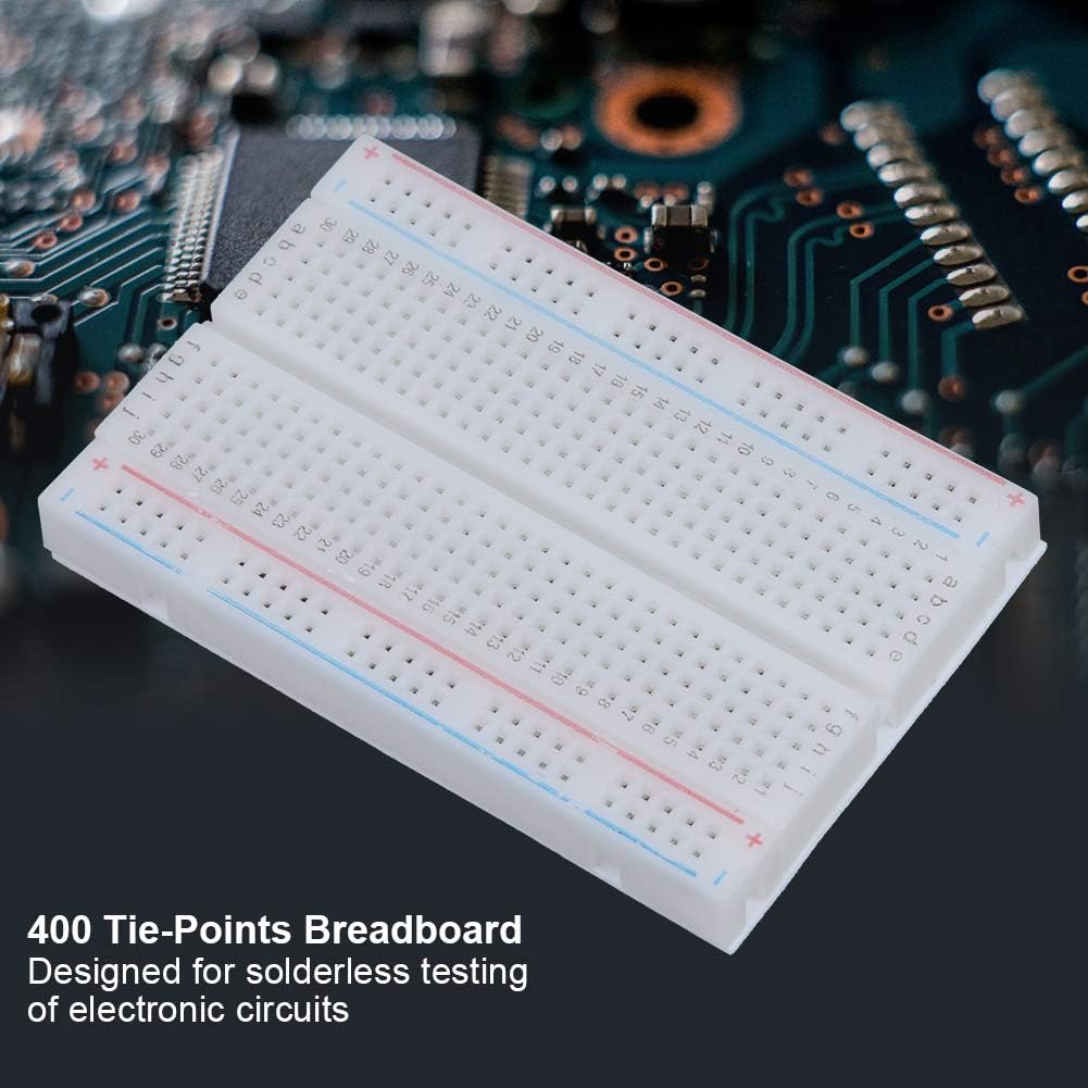
Figure 3: Angled view highlighting the 400 tie points, designed for solderless testing of electronic circuits.
3. Operating Principles
The AYNEFY breadboard facilitates rapid prototyping and experimentation. Its solderless nature means you can quickly build, test, and modify circuits.
3.1 Building a Circuit Prototype
To build a circuit, follow these general steps:
- Design: Start with a circuit diagram or schematic.
- Power Connections: Connect your power supply (e.g., battery pack, DC adapter) to the power rails (+ and -) on the breadboard.
- Component Placement: Insert components into the terminal strips according to your circuit design. Remember that holes in the same row (a-e or f-j) are connected.
- Interconnections: Use jumper wires to connect different components and sections of the breadboard as required by your circuit diagram. Ensure connections are firm but not forced.
- Testing: Once assembled, apply power and test your circuit. If it doesn't work as expected, you can easily remove and re-position components or jumper wires for debugging.
The ability to quickly modify connections makes the breadboard an invaluable tool for learning and iterative design.

Figure 4: The breadboard in an angled view, emphasizing its solderless nature and high quality for extended service life.
4. Maintenance and Care
Proper care of your AYNEFY Solderless Breadboard will ensure its longevity and reliable performance.
- Keep Clean: Dust and debris can accumulate in the holes, potentially affecting connections. Use compressed air or a soft brush to clean the breadboard regularly.
- Avoid Force: Do not force component leads or jumper wires into the holes. If a lead doesn't insert easily, check for obstructions or try a different hole. Excessive force can damage the internal metal clips.
- Proper Storage: Store the breadboard in a clean, dry environment away from extreme temperatures and direct sunlight. Consider using a dust cover or a sealed container when not in use.
- Inspect Regularly: Periodically check the breadboard for any visible damage, such as cracked plastic or bent pins.
5. Troubleshooting
If your circuit is not functioning as expected on the breadboard, consider the following common troubleshooting steps:
- Check Power Connections: Ensure your power supply is correctly connected to the power rails (+ and -) and that the power rails are connected to your circuit where needed. Verify the power supply is on and providing the correct voltage.
- Verify Component Placement: Double-check that all components are inserted into the correct holes and that their leads are making good contact. Ensure ICs are correctly oriented and straddling the central channel.
- Inspect Jumper Wires: Ensure all jumper wires are firmly inserted and connect the intended points. Loose or incorrect jumper wire connections are a very common source of errors.
- Review Circuit Diagram: Compare your physical breadboard layout against your circuit diagram or schematic. A single misplaced wire or component can prevent the entire circuit from working.
- Test Components Individually: If possible, test individual components off the breadboard to ensure they are functional.
- Check for Short Circuits: Ensure no component leads or wires are accidentally touching, creating unintended short circuits.
6. Specifications
Detailed specifications for the AYNEFY 400 Tie Points Mini Solderless Breadboard:
| Attribute | Value |
|---|---|
| Plastic Part Material | ABS |
| Color | White |
| Tie Points | 400 holes |
| Terminal Strips | 1 (300 tie points) |
| Distribution Bars | 2 (100 tie points) |
| Matching Jumper Wire Diameter | 0.8mm |
| Size (L x W) | 85 x 55mm / 3.3 x 2.2in |
| Item Weight | 1.59 ounces |
| Product Dimensions | 3.35 x 2.17 x 0.31 inches |
| Manufacturer | AYNEFY |
| Part Number | AYNEFYgps0g5uqwy |
Ask a question about this manual
Ask about setup, troubleshooting, compatibility, parts, safety, or missing instructions. Manuals+ will review the question and use this page’s manual context to help answer it.