1. Introduction
This instruction manual provides essential information for the safe and effective installation, operation, and maintenance of the ZLB Softstart Module 230V 16A. This module is designed to enhance the performance and longevity of electric tools equipped with brush motors by reducing the initial inrush current during startup. Please read this manual thoroughly before installation and retain it for future reference.
2. Product Overview
The ZLB Softstart Module is an electrical component engineered to provide a delayed, gradual startup for electric tools. This 'soft start' functionality significantly reduces the high current surge that typically occurs when a motor is switched on. By mitigating this inrush current, the module helps to:
- Protect the tool's internal components, such as gears and bearings, from excessive mechanical stress.
- Minimize electrical load on the power supply, preventing circuit breaker trips.
- Improve user comfort by reducing the sudden jolt or kickback of the tool at startup.
The module is compatible with a wide range of electric tools featuring brush motors, including angle grinders, table saws, hand circular saws, routers, miter saws, and chop saws, from various manufacturers.
3. Safety Instructions
WARNING: Electrical work should only be performed by qualified personnel. Always disconnect the power supply to the tool before attempting any installation or maintenance.
- Ensure the power tool is unplugged from the mains before beginning installation.
- Verify that the voltage and current ratings of the softstart module (230V, 16A, max 3500W) match or exceed the requirements of your power tool.
- The module's housing may carry live voltage. Install the module in a location within the tool where it cannot be accidentally touched during operation.
- Ensure adequate ventilation for the module to prevent overheating. Do not enclose it in a way that restricts airflow.
- Use appropriate connectors for your tool's wattage. Red flat connectors are suitable only for machines up to 2200 watts. For tools exceeding 2200 watts, use Wago clamps or solder connections.
- All connections must be secure and properly insulated to prevent short circuits and electrical hazards.
4. Package Contents
The ZLB Softstart Module package includes the following components:
- 1 x ZLB Softstart Module 16A
- 2 x Wago Clamps 221-412
- 1 x Wago Clamp 221-413
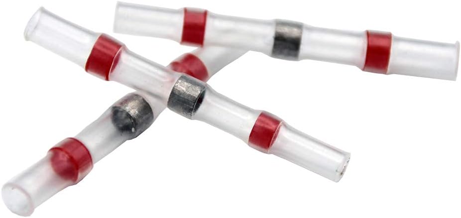
- 3 x Red Solder Connections
- 6 x Red Insulated Flat Connectors (3 male, 3 female) - Note: For machines up to 2200W only.
- 3 x Cable Extensions (red, blue, black), 13 cm each, Lapp Litze H05V-K 300/500 V

5. Setup and Installation
The softstart module must be installed in the power tool's electrical circuit after the main power switch. Installing it before the switch will render the softstart function ineffective, as the module needs to be powered only when the switch is engaged.
5.1. General Installation Steps
- Disconnect Power: Ensure the power tool is unplugged from the electrical outlet.
- Access Tool Wiring: Carefully open the housing of your power tool to access its internal wiring. Refer to your tool's specific service manual if necessary.
- Identify Motor Connection: Locate the power wires leading from the tool's switch to the motor. The softstart module needs to be inserted into this circuit.
- Wiring the Module: Follow the wiring diagram provided below. The module has three wires: red, blue, and black.
- Select Connectors: Choose the appropriate connectors from the included set based on your tool's wattage. For tools up to 2200W, red flat connectors can be used. For tools over 2200W, use the Wago clamps or solder connections for a more robust connection.
- Secure Connections: Make all electrical connections secure and ensure they are properly insulated. Use heat shrink tubing for solder connections if possible.
- Position Module: Place the softstart module within the tool's housing, ensuring it has adequate space for ventilation and does not interfere with moving parts. The module's housing should not be accessible to touch during normal operation.
- Reassemble Tool: Carefully close and secure the tool's housing.
- Test: Plug the tool back into the power outlet and test its operation. The motor should now start with a noticeable delay and a smoother ramp-up to full speed.
5.2. Wiring Diagram

Connection Details:
- The module's red wire (A) connects to the live wire coming from the tool's switch.
- The module's blue wire (C) connects to the neutral wire of the power supply.
- The module's black wire (B) connects to the motor's other terminal.

5.3. Connector Usage
The kit includes various connectors for different installation needs:
- Wago Clamps: Ideal for secure, tool-free connections, especially for higher wattage tools (above 2200W).
- Solder Connections: Provide the most permanent and robust electrical connection, recommended for high-power applications (above 2200W).
- Red Flat Connectors: Suitable for machines up to 2200 watts. Ensure a tight fit.


6. Operating Principles
Once correctly installed, the ZLB Softstart Module operates automatically. When the power tool's switch is activated, the module gradually increases the voltage and current supplied to the motor over a short period (typically a few seconds). This controlled ramp-up prevents the sudden surge of electricity that can stress the motor and electrical system. No further user interaction is required for the softstart function to engage.
7. Maintenance
The ZLB Softstart Module is designed to be maintenance-free. However, periodic inspection of the installation is recommended, especially if the tool is used frequently or in demanding conditions.
- Check Connections: Ensure all electrical connections remain secure and free from corrosion.
- Inspect Wiring: Look for any signs of wear, fraying, or damage to the module's wires or the tool's internal wiring.
- Ensure Ventilation: Confirm that the module's placement within the tool still allows for adequate airflow to prevent heat buildup.
- Keep Clean: If accessible, ensure the module and its surroundings are free from dust and debris.
8. Troubleshooting
If the softstart module does not appear to be functioning correctly, consider the following:
- No Softstart Effect:
- Verify that the module is installed after the tool's power switch. Incorrect placement will bypass the softstart function.
- Check all wiring connections for proper contact and insulation.
- Ensure the module is receiving power when the tool's switch is activated.
- Tool Not Starting:
- Check all electrical connections for looseness or disconnections.
- Ensure the tool's power supply is active and the circuit breaker has not tripped.
- Temporarily bypass the softstart module (if safely possible) to determine if the issue lies with the module or the tool itself.
- Module Overheating:
- Ensure the module has sufficient airflow and is not enclosed in a tight space without ventilation.
- Verify that the tool's wattage does not exceed the module's maximum capacity of 3500W.
- Inconsistent Operation:
- Inspect for any intermittent connections or damaged wiring.
- Ensure the correct type of connectors (Wago clamps or solder) are used for tools over 2200W.
If problems persist after troubleshooting, contact the manufacturer or a qualified electrician.
9. Specifications
| Feature | Specification |
|---|---|
| Manufacturer | ZLB |
| Model Number | unifun (KR230-16A) |
| Dimensions (L x W x H) | 53mm x 35mm x 15mm |
| Voltage | 230 Volt AC (VAC) |
| Maximum Current | 16 Ampere |
| Maximum Wattage | 3500 Watt |
| Phase Type | Single-phase |
| Special Features | 3 cables (Tirac) |
| Batteries Required | No |
10. Warranty and Support
Specific warranty information for the ZLB Softstart Module is not provided in this manual. For details regarding warranty coverage, return policies, or technical support, please refer to the product's original purchase documentation or contact the seller directly. You may also visit the ZLB manufacturer's official website for further assistance.


