
1. Introduction
The MATRIX MPS-3005H-3 is a high-precision triple linear DC power supply designed for laboratory and industrial applications. It features adjustable voltage and current outputs, low ripple, and a 4-digit display for accurate readings. This manual provides essential information for the safe and efficient operation of your device.

Figure 1.1: The MATRIX MPS-3005H-3 power supply is suitable for experimental testing, production line detection, electronic engineering, and aviation applications.

Figure 1.2: This linear power supply offers a three-way power output with options for 3A, 5A, or 10A, and a resolution of 10mV/1mA.
2. Safety Information
To ensure safe operation and prevent damage to the unit or injury to personnel, please observe the following safety precautions:
- Always connect the grounding wire before operation.
- Do not operate the power supply in wet or damp conditions.
- Ensure proper ventilation to prevent overheating. The built-in smart cooling fan helps maintain optimal operating temperature.
- Avoid short circuits at the output terminals. The unit includes overcurrent protection, overvoltage protection, and short circuit protection.
- Do not attempt to repair or modify the unit. Refer all servicing to qualified personnel.
- Verify input voltage (110V/220V) switch setting on the rear panel matches your local power supply before connecting.
3. Product Overview
The MPS-3005H-3 features a user-friendly front panel with clear displays and intuitive controls.

Figure 3.1: Front panel of the MATRIX MPS-3005H-3, showing the main unit, test leads, and power cord.
3.1 Front Panel Layout

Figure 3.2: Detailed view of the front panel, highlighting Channel 1 (CH1) and Channel 2 (CH2) voltage and current displays, adjustment knobs, mode indicators (CC/CV), output switches, and output terminals. CH3 indicator light is also shown.
- Display: 4-digit display for voltage (V) and current (A) for CH1 and CH2. The voltage display has been upgraded for better brightness and readability.
- Adjustment Knobs: Separate knobs for current (OCP) and voltage (OVP) adjustment for each channel. These are coded switch knobs for precise fine and coarse adjustments.
- Mode Indicators: CC (Constant Current) and CV (Constant Voltage) indicators.
- Output Switches: Independent ON/OFF switches for CH1 and CH2 outputs.
- Output Terminals: Binding posts for connecting loads.
- Multifunction Button: Used for selecting series/parallel modes and accessing advanced settings.
- CH3 Output: A fixed 5V/3A output channel.

Figure 3.3: This image illustrates the three sets of output terminals and the multifunction button for independent, series, or parallel operation.
3.2 Rear Panel Features

Figure 3.4: Rear panel view, showing the power outlet, fuse holder, 110V/220V input switch, and intelligent temperature control fan.
- Power Outlet: For connecting the AC power cord.
- Fuse Holder: Contains the protective fuse.
- 110V/220V Input Switch: Selects the appropriate input voltage.
- Intelligent Temperature Control Fan: Activates automatically to cool the unit during operation.
4. Setup
Follow these steps for initial setup of your power supply:
- Unpacking: Carefully remove the power supply and all accessories from the packaging. Verify all components are present: Linear DC Power Supply (1), Power cord (1), Test lines (3), and User Manual (1).
- Placement: Place the unit on a stable, level surface with adequate ventilation. Ensure the intelligent temperature control fan on the rear panel is not obstructed.
- Voltage Selection: Before connecting the power cord, check the 110V/220V input switch on the rear panel. Set it to match your local power supply voltage.
- Power Connection: Connect the provided power cord to the power outlet on the rear panel and then to a grounded AC power source.
- Initial Power On: Press the main power switch on the front panel to turn on the unit. The display will illuminate.

Figure 4.1: The complete set of accessories includes the power supply unit, test leads, power cord, and user manual.
5. Operating Instructions
This section details the operation of the MATRIX MPS-3005H-3, including setting voltage and current, and utilizing its various output modes.
5.1 Setting Voltage and Current
- Ensure the output switches for CH1 and CH2 are in the OFF position.
- Use the respective voltage adjustment knobs for CH1 and CH2 to set the desired output voltage. Rotate clockwise to increase, counter-clockwise to decrease.
- Use the respective current adjustment knobs for CH1 and CH2 to set the desired output current limit.
- Press the output switch for the desired channel (CH1 or CH2) to enable the output. The corresponding indicator light will illuminate.

Figure 5.1: The coded switch knobs allow for quick and easy push-in adjustments, facilitating both fine and coarse tuning of voltage and current.
5.2 Overvoltage Protection (OVP) and Overcurrent Protection (OCP) Setting
To set OVP and OCP limits:
- Long press the voltage adjustment knob (for OVP) or current adjustment knob (for OCP) for the desired channel. The display will show "OFF" or the current setting.
- Rotate the knob to set the desired OVP or OCP value.
- Short press the knob to exit the setting mode.
5.3 Series and Parallel Modes
The power supply supports series and parallel operation for increased voltage or current output.
- Series Mode: Press the multifunction button on the left side of the front panel until "SE" (Series) is displayed. In this mode, connect the positive terminal of CH1 to the negative terminal of CH2 using a short lead. The total voltage will be the sum of CH1 and CH2 voltages, while the current remains the current of the master channel.
- Parallel Mode: Press the multifunction button until "PA" (Parallel) is displayed. In this mode, connect the positive terminals of CH1 and CH2 together, and the negative terminals of CH1 and CH2 together. The total current will be the sum of CH1 and CH2 currents, while the voltage remains the voltage of the master channel.
Video 5.1: This video demonstrates the operation of the MPS-3005H-3, including setting voltage and current, and configuring series and parallel modes. It shows the precision of the output compared to an external multimeter.
5.4 Fixed 5V/3A Output (CH3)
The CH3 output provides a fixed 5V/3A supply, suitable for powering standard 5V devices. This output is always active when the unit is powered on and does not have independent controls.
6. Maintenance
Proper maintenance ensures the longevity and reliable operation of your power supply.
- Cleaning: Use a soft, dry cloth to clean the exterior of the unit. Do not use abrasive cleaners or solvents.
- Ventilation: Regularly check that the air vents and the intelligent temperature control fan are free from dust and obstructions.
- Storage: When not in use for extended periods, store the power supply in a cool, dry environment, away from direct sunlight and excessive dust.
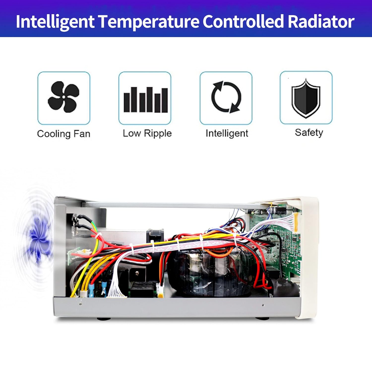
Figure 6.1: The internal intelligent temperature controlled radiator and cooling fan system ensures efficient heat dissipation, contributing to product longevity and low ripple output.
7. Troubleshooting
This section addresses common issues you might encounter with your power supply.
| Problem | Possible Cause | Solution |
|---|---|---|
| No power/display off | Power cord disconnected, fuse blown, or main power switch off. | Check power cord connection, replace fuse if blown, ensure main power switch is ON. |
| No output voltage/current | Output switch OFF, OVP/OCP triggered, or load disconnected. | Turn output switch ON, check OVP/OCP settings, verify load connection. |
| Display shows "OFF" for OVP/OCP | OVP/OCP function is disabled. | Long press the respective knob to enter setting mode and enable/set the protection. |
| Dim green voltage display | Possible display issue (some early models). | Contact MATRIX customer support for assistance or potential display replacement. |
| Unexpected voltage overshoot on output switch | Specific behavior related to CC mode activation upon output enable. | Ensure load can handle brief voltage spikes or enable output before connecting sensitive loads. Consider adjusting current settings. |
8. Specifications
| Feature | Detail |
|---|---|
| Brand | MATRIX |
| Model Name | MPS-3005H-3 |
| Output Wattage | 315 Watts |
| Current Rating | 5 Amps |
| Form Factor | Benchtop |
| Cooling Method | Air (Intelligent Temperature Control Fan) |
| Voltage Accuracy | 0.03%+10mV |
| Current Accuracy | 0.1%+5mA |
| Display | 4-digit (effectively 5-digit precision) |
| Protection Functions | Overheat protection, Overvoltage protection (OVP), Overcurrent protection (OCP), Short circuit protection. |
| Dimensions | 17 x 14 x 9.7 inches (Package) |
| Weight | 23.1 Pounds (Package) |
| UPC | 710323810582 |
9. Warranty and Support
The MATRIX MPS-3005H-3 comes with a 3-year warranty, ensuring peace of mind for your investment. For any technical assistance, troubleshooting not covered in this manual, or warranty claims, please contact MATRIX customer support.
Manufacturer: MATRIX TECHNOLOGY INC.
For further support, visit the Official MATRIX Store on Amazon.


