1. Introduction
This user manual provides detailed instructions for the safe and effective operation of your AstroAI Digital Clamp Meter Multimeter CM2K0R. This versatile tool is designed for measuring AC current, AC/DC voltage, resistance, capacitance, continuity, and performing live wire and non-contact voltage tests. Please read this manual thoroughly before use and retain it for future reference.

Figure 1: The AstroAI Digital Clamp Meter CM2K0R, including test leads, two AAA batteries, and a protective carrying case.
2. Safety Information
Always adhere to the following safety precautions to prevent personal injury or damage to the meter.
- Do not attempt to measure DC current with this device. It is designed for AC current measurement only.
- Ensure the meter is set to the correct function and range before making any measurements.
- Do not use the meter if it appears damaged or if the test leads are compromised.
- Observe all safety warnings and instructions provided in this manual.
- The meter is rated for environmental pollution degree 2 and overvoltage category III 600V. Do not exceed these ratings.
- Always disconnect power to the circuit before measuring resistance, capacitance, or continuity.
- Use caution when working with voltages above 60V DC or 30V AC RMS, as they pose a shock hazard.
3. Product Overview
3.1 Components
Familiarize yourself with the parts of your AstroAI Digital Clamp Meter:

Figure 2: Labeled diagram of the AstroAI Digital Clamp Meter CM2K0R, showing key components.
- NCV Detector: Used for Non-Contact Voltage detection.
- Transformer Jaws: For clamping around a conductor to measure AC current.
- Flashlight: Illuminates the measurement area.
- Trigger: Opens the transformer jaws.
- FUNC Button: Selects different functions within a rotary switch position.
- Flashlight Button: Activates the built-in flashlight.
- Display: LCD screen showing measurement readings and indicators.
- COM Terminal: Common input for test leads (black).
- INPUT Terminal: Positive input for test leads (red).
- DATA HOLD Button: Freezes the current display reading.
- Rotary Switch: Selects the primary measurement function.
- Indicator Light: Provides visual feedback for NCV and Live Wire tests.
- MAX/MIN Button: Displays maximum or minimum measured values.
- Backlight Button: Turns the display backlight on or off.
3.2 Display Indicators
The LCD displays various symbols and readings:
- AC/DC: Indicates Alternating Current or Direct Current measurement.
- V: Volts (Voltage).
- A: Amperes (Current).
- Ω: Ohms (Resistance).
- F: Farads (Capacitance).
- Hz: Hertz (Frequency).
- Continuity Symbol: Indicates continuity test mode.
- Diode Symbol: Indicates diode test mode.
- NCV: Non-Contact Voltage detection mode.
- LIVE: Live Wire test mode.
- HOLD: Data Hold function active.
- MAX/MIN: Maximum or Minimum value display.
- Battery Symbol: Low battery indicator.
4. Setup
4.1 Battery Installation
The meter requires two 1.5V AAA batteries for operation.
- Locate the battery compartment cover on the back of the meter.
- Use a screwdriver to remove the screw securing the cover.
- Insert two 1.5V AAA batteries, ensuring correct polarity (+ and -).
- Replace the battery compartment cover and secure it with the screw.
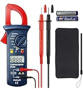
Figure 3: Image showing the open battery compartment of the AstroAI Digital Clamp Meter CM2K0R with two AAA batteries inserted.
5. Operating Instructions
To begin, turn the rotary switch to the desired measurement function. Connect the test leads as instructed for specific measurements.
5.1 AC/DC Voltage Measurement
- Turn the rotary switch to the "V~" (AC Voltage) or "V-" (DC Voltage) position.
- Insert the red test lead into the INPUT terminal and the black test lead into the COM terminal.
- Connect the test probes across the circuit or component to be measured.
- Read the voltage value on the display.
5.2 AC Current Measurement
Important: This meter measures AC current only. Do not attempt to measure DC current with the clamp jaws.
- Turn the rotary switch to the "A~" (AC Current) position.
- Press the trigger to open the transformer jaws.
- Clamp the jaws around a single conductor (not a bundle of wires) of the circuit.
- Ensure the jaws are fully closed.
- Read the AC current value on the display.

Figure 4: The clamp meter jaws are shown clamped around a single live wire to measure AC current, with the reading visible on the display.
5.3 Resistance Measurement
- Turn the rotary switch to the "Ω" (Resistance) position.
- Insert the red test lead into the INPUT terminal and the black test lead into the COM terminal.
- Connect the test probes across the component to be measured. Ensure the circuit is de-energized.
- Read the resistance value on the display.
5.4 Capacitance Measurement
- Turn the rotary switch to the "F" (Capacitance) position.
- Insert the red test lead into the INPUT terminal and the black test lead into the COM terminal.
- Connect the test probes across the capacitor. Ensure the capacitor is discharged before testing.
- Read the capacitance value on the display.
5.5 Continuity Test
- Turn the rotary switch to the continuity symbol position.
- Insert the red test lead into the INPUT terminal and the black test lead into the COM terminal.
- Connect the test probes across the circuit or component. Ensure the circuit is de-energized.
- If continuity exists (resistance below approximately 50Ω), the buzzer will sound.
5.6 Diode Test
- Turn the rotary switch to the diode symbol position.
- Insert the red test lead into the INPUT terminal and the black test lead into the COM terminal.
- Connect the red probe to the anode and the black probe to the cathode of the diode.
- Read the forward voltage drop on the display. Reverse the probes to check for open circuit (OL).
5.7 Live Wire Test
- Turn the rotary switch to the "NCV/LIVE" position.
- Press the FUNC button to select "LIVE" mode.
- Place the red test probe into the socket or near the wire to be tested.
- The meter will indicate the presence of a live wire with an audible beep and a visual indicator.

Figure 5: The clamp meter's probe is shown near a wire, indicating a live wire test in progress with a buzzing sound.
5.8 Non-Contact Voltage (NCV) Detection
- Turn the rotary switch to the "NCV/LIVE" position.
- Bring the NCV detector (top part of the clamp jaws) close to the conductor or outlet.
- The meter will detect AC voltage without physical contact.
- A weak AC signal will trigger a green indicator light and slow beep. A strong AC signal will trigger a red indicator light and quick beep.

Figure 6: The clamp meter is held near an electrical outlet, demonstrating non-contact voltage detection with visual indicators for high and low voltage.
6. Additional Features
- Data Hold: Press the "HOLD" button to freeze the current reading on the display. Press again to release.
- MAX/MIN: Press the "MAX/MIN" button to display the maximum or minimum measured value during a measurement session.
- Auto Shut-off: The meter will automatically power off after approximately 15 minutes of inactivity to conserve battery life.
- Low Battery Indicator: A battery symbol will appear on the display when the battery voltage is low, indicating that batteries should be replaced.
- Backlight: Press the "Backlight" button to illuminate the display for better visibility in low-light conditions.
- Flashlight: Press the "Flashlight" button to turn on the built-in flashlight.
7. Maintenance
- Cleaning: Wipe the meter with a damp cloth and mild detergent. Do not use abrasives or solvents.
- Battery Replacement: Replace batteries when the low battery indicator appears. Refer to Section 4.1 for instructions.
- Storage: If the meter is not used for an extended period, remove the batteries to prevent leakage. Store in a cool, dry place.
8. Troubleshooting
- Meter does not power on: Check battery installation and ensure batteries are not depleted.
- Inaccurate readings: Ensure the correct function is selected and test leads are properly connected. Verify the circuit is de-energized for resistance/continuity tests. For AC current, ensure only one conductor is within the clamp jaws.
- No continuity beep: Check if the circuit is de-energized and the resistance is below the threshold (approx. 50Ω).
- For further assistance, please contact AstroAI customer support.
9. Specifications
| Parameter | Value |
|---|---|
| Brand | AstroAI |
| Model Number | CM2K0R |
| Measurement Type | Multimeter |
| Display Counts | 2000 Counts |
| Power Source | Battery Powered (2 AAA batteries required) |
| Product Dimensions | 6.81 x 2.9 x 19.48 cm |
| Item Weight | 386 Grams |
| Min. Operating Voltage | 1.5 Volts |
| Maximum Operating Voltage | 600 Volts |
| Safety Standard Met | Pollution Level 2, Surge Category III 600 V |
| Country of Origin | China |

Figure 7: Diagram illustrating the dimensions of the AstroAI Digital Clamp Meter CM2K0R, showing length, width, and jaw opening size.
10. Warranty and Support
AstroAI provides professional technical support. If you have any questions about the product, its operation, or require assistance, please contact our support team. Our California-based support team will respond within 24 hours.
Contact Information:
- Email: support@astroai.com
- For more information, visit the official AstroAI store: AstroAI Store


