1. Introduction
The Whadda WSG105 Junior Theremin is an electronic soldering kit designed for educational purposes and hobbyists. Upon successful assembly, this kit creates a functional Junior Theremin, an electronic musical instrument that produces sound based on the proximity of a hand to its antenna. It allows users to explore basic electronics, soldering techniques, and the principles of early electronic music synthesis.
This manual provides detailed instructions for assembling, operating, and maintaining your Junior Theremin kit. Please read all instructions carefully before beginning assembly.
2. Safety Information
Warning: This kit involves soldering, which uses high temperatures and produces fumes. Always follow these safety guidelines:
- Work in a well-ventilated area to avoid inhaling solder fumes.
- Wear appropriate eye protection (safety glasses) to protect against splashes or flying debris.
- Use a soldering iron stand to prevent accidental burns.
- Avoid touching the hot tip of the soldering iron.
- Keep flammable materials away from your work area.
- Wash hands thoroughly after handling solder, especially lead-based solder.
- Ensure the power supply (9V battery) is connected correctly to prevent damage to the circuit or battery.
3. Package Contents
Before starting assembly, verify that all components listed below are present in your kit.

Figure 1: All components included in the Whadda WSG105 Junior Theremin Soldering Kit, laid out for inspection. This includes the printed circuit board (PCB), various resistors, capacitors, integrated circuits (ICs), a speaker, battery clip, push buttons, LEDs, and the antenna wire.
- Printed Circuit Board (PCB)
- Integrated Circuits (ICs) and Sockets
- Resistors (various values)
- Capacitors
- LEDs (Light Emitting Diodes)
- Push Buttons
- Piezo Speaker
- Battery Clip (for 9V battery)
- Antenna Wire
- Voltage Regulator (REG)
Note: A 9V battery is required for operation and is not included in the kit.
4. Assembly Instructions (Setup)
Follow these steps carefully to assemble your Junior Theremin. It is recommended to solder components from lowest height to highest height.
4.1 Tools Required
- Soldering Iron
- Solder (rosin core recommended)
- Wire Cutters/Nippers
- Small Pliers
- Safety Glasses
- Desoldering Braid or Pump (optional, for corrections)
4.2 Soldering Process
- Identify Components: Before soldering, identify all components. Resistors have color bands indicating their value. Capacitors and LEDs are polarized; ensure correct orientation.
- Solder Resistors: Start by inserting the resistors into their designated spots on the PCB (R1-R7). Bend the leads slightly on the underside to hold them in place. Solder each lead, ensuring a shiny, cone-shaped joint. Trim excess leads with wire cutters.
- Solder IC Sockets: Place the IC sockets (for IC1 and IC2) onto the PCB. Ensure the notch on the socket aligns with the notch indicated on the PCB silkscreen. Solder all pins.
- Solder Capacitors: Insert the capacitors (C1-C3). Pay attention to polarity for electrolytic capacitors (if present, usually marked with a stripe for the negative lead). Solder and trim leads.
- Solder LEDs: Insert the LEDs (LED1-LED4). LEDs are polarized; the longer lead is typically the anode (+) and the shorter lead is the cathode (-). The PCB usually indicates polarity. Solder and trim leads.
- Solder Push Buttons: Place the push buttons into their positions. Solder all pins.
- Solder Voltage Regulator (REG): Insert the voltage regulator. Ensure correct orientation as indicated on the PCB. Solder its pins.
- Solder Piezo Speaker: Connect the piezo speaker to its designated pads. Polarity might be indicated, but for a simple piezo speaker, it's often less critical than other components.
- Solder Battery Clip: Attach the red wire of the 9V battery clip to the '+' pad and the black wire to the '-' pad on the PCB. Ensure correct polarity.
- Solder Antenna Wire: Connect the antenna wire to the designated "ANT" pad on the PCB. This wire will act as the sensing element for the Theremin.
- Insert ICs: Carefully insert the Integrated Circuits (ICs) into their respective sockets (IC1, IC2). Ensure the notch on the IC aligns with the notch on the socket and the PCB. Bend the pins slightly inward if necessary to fit into the socket. Apply gentle, even pressure to seat them fully.
- Visual Inspection: After all components are soldered, carefully inspect the PCB for any cold solder joints (dull, lumpy appearance), solder bridges (solder connecting two adjacent pads), or incorrectly oriented components. Correct any issues before proceeding.

Figure 2: A fully assembled Whadda WSG105 Junior Theremin circuit board, showing all components soldered in place, including the speaker, ICs, LEDs, buttons, and antenna wire.

Figure 3: An example of a person engaged in the soldering process, demonstrating the use of a soldering iron and proper technique for attaching components to a circuit board.
5. Operating Instructions
Once assembled, your Junior Theremin is ready for use.
- Connect Power: Attach a fresh 9V battery to the battery clip. The Theremin should power on.
- Initial Sound: The Theremin may produce a continuous tone upon power-up.
- Adjust Pitch: Slowly move your hand towards and away from the antenna wire. Observe how the pitch of the sound changes. Moving your hand closer typically increases the pitch, while moving it away decreases it.
- Mode Buttons: Use the '+' and '-' buttons on the PCB to adjust settings or modes, such as octave range or sensitivity, if implemented in the circuit design. Refer to the specific circuit diagram for detailed button functionality.
- LED Indicators: The LEDs (LED1-LED4) may indicate the current pitch or mode, providing visual feedback during operation.
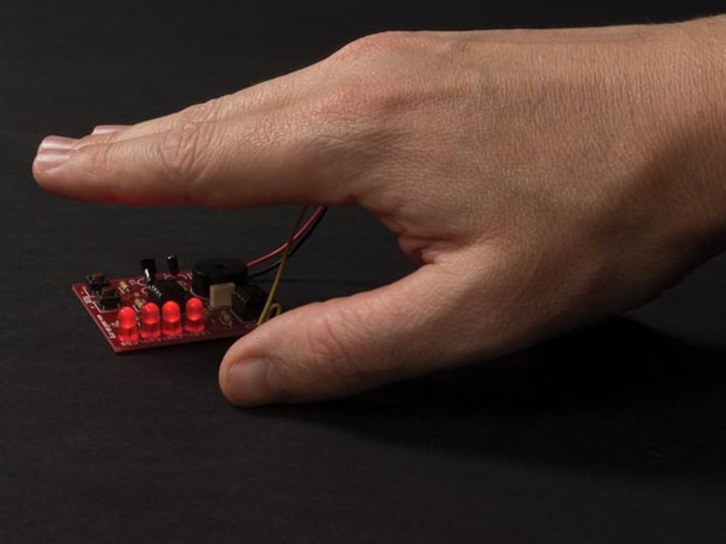
Figure 4: A hand positioned above the assembled Junior Theremin, demonstrating the interaction with the antenna to control the pitch of the sound.
6. Maintenance
- Cleaning: Keep the circuit board clean and free of dust. Use a soft, dry brush or compressed air to remove debris. Avoid using liquids.
- Battery Replacement: Replace the 9V battery when the sound becomes weak or inconsistent. Always disconnect the battery when the device is not in use for extended periods to prevent discharge.
- Storage: Store the Theremin in a dry, cool place, away from direct sunlight and extreme temperatures.
- Solder Joint Inspection: Periodically inspect solder joints for any signs of cracking or corrosion, especially if the device is handled frequently. Re-solder any compromised joints if necessary.
7. Troubleshooting
| Problem | Possible Cause | Solution |
|---|---|---|
| No sound or very faint sound. |
|
|
| Sound is constant and does not change with hand movement. |
|
|
| Intermittent sound or erratic behavior. |
|
|
8. Specifications
- Model: WSG105
- Power Supply: 9V DC (battery not included)
- Dimensions (assembled PCB): Approximately 50 x 50 x 12 mm (1.9 x 1.9 x 0.5 inches)
- Function: Electronic musical instrument (Theremin) with pitch control via hand proximity.
- Manufacturer: Velleman (Whadda brand)
- Usage: Amateur, educational soldering kit.
9. Warranty and Support
This Whadda WSG105 Junior Theremin Soldering Kit is provided as a DIY educational product. Due to the nature of self-assembly and soldering, specific warranties on the assembled product may vary. Please refer to the manufacturer's official website or the retailer's policy for detailed warranty information regarding individual components or the kit itself.
For technical support or inquiries regarding missing components, please contact Whadda customer service or the retailer from whom the kit was purchased.


