1. Introduction
Thank you for choosing the BSIDE ACM92 Mini Clamp Meter. This device is a compact, auto-ranging digital multimeter designed for accurate measurement of AC/DC current, AC/DC voltage, resistance, and frequency. It also features non-contact voltage detection and continuity testing. Please read this manual thoroughly before operation to ensure safe and correct usage.
Safety Information: Always adhere to safety precautions when working with electrical circuits. Incorrect use can lead to electric shock or damage to the meter. This device conforms to IEC-61010-1, IEC-61010-2-030, IEC-61010-2-032, IEC-61010-2-033 standards and has over-voltage protection class CAT III 300V, CAT II 600V, pollution degree II.
2. Product Overview
2.1 Components
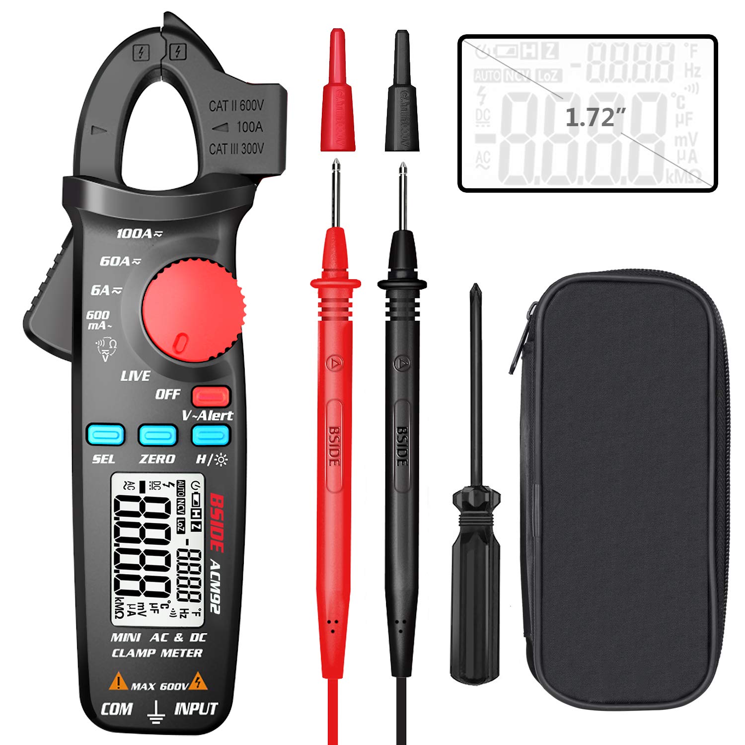
This image displays the BSIDE ACM92 Mini Clamp Meter along with its standard accessories. Included are the clamp meter unit, a pair of test probes (red and black), a carrying bag for protection and portability, and a small screwdriver for battery compartment access.
2.2 Key Features
- Measures AC Current (minimum 0.1mA by jaws)
- Measures DC Current (minimum 1mA by jaws)
- Measures AC/DC Voltage
- V-Alert (Non-Contact Voltage Detection) and Live-Wire Check
- Measures Frequency, Resistance, and Continuity
- Clamp-on Frequency Function
- Auto Power Off for battery conservation
- Data Hold function
- Low Battery Indication
- Backlight for improved visibility in dark environments
- 20mm jaw capacity with side probe holder
3. Setup
3.1 Battery Installation
- Ensure the meter is powered off.
- Locate the battery compartment cover on the back of the meter.
- Use the provided screwdriver to loosen the screw securing the battery cover.
- Remove the cover.
- Insert two 1.5V AAA batteries, observing the correct polarity (+/-).
- Replace the battery cover and tighten the screw.
4. Operating Instructions
4.1 Power On/Off
Rotate the rotary switch from 'OFF' to any desired measurement function to power on the meter. To power off, rotate the switch back to 'OFF'. The meter will automatically power off after 20 minutes of inactivity.
4.2 Measuring DC Current

This image illustrates the BSIDE ACM92 Mini Clamp Meter being used to measure DC current. The clamp jaws are placed around a single conductor connected to a car battery, and the display shows a current reading.
- Rotate the rotary switch to the '6A/60A/100A' DC current range.
- Press the 'ZERO' button to zero out any residual magnetic field before measurement.
- Open the clamp jaws and enclose only one conductor (not a bundle of wires).
- Read the DC current value on the display.
4.3 Measuring AC Current
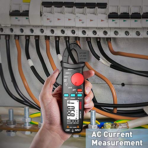
This image shows the BSIDE ACM92 Mini Clamp Meter measuring AC current. The clamp jaws are positioned around a single live wire within an electrical distribution panel, with the measurement displayed on the screen.
- Rotate the rotary switch to the '600mA' or '6A/60A/100A' AC current range.
- Open the clamp jaws and enclose only one conductor.
- Read the AC current value on the display.
4.4 Measuring AC/DC Voltage
- Insert the red test probe into the 'INPUT' jack and the black test probe into the 'COM' jack.
- Rotate the rotary switch to the 'V' (Voltage) function. The meter will automatically detect AC or DC voltage.
- Connect the test probes in parallel to the circuit or component to be measured.
- Read the voltage value on the display.
4.5 V-Alert (Non-Contact Voltage Detection)

This image demonstrates the V-Alert function of the BSIDE ACM92 Mini Clamp Meter. The meter is held near an electrical circuit breaker, and its display shows 'V-Alert' with a flashing indicator, signifying the detection of AC voltage without direct contact.
- Rotate the rotary switch to the 'V-Alert' position.
- Bring the top end of the meter near the conductor or outlet.
- If AC voltage is detected, the LCD display will flash, and an alarm buzzer will sound.
4.6 Measuring Resistance
- Insert the red test probe into the 'INPUT' jack and the black test probe into the 'COM' jack.
- Rotate the rotary switch to the 'Ω' (Resistance) function.
- Ensure the circuit or component is de-energized before connecting the probes.
- Connect the test probes across the component to measure its resistance.
- Read the resistance value on the display.
4.7 Continuity Test
- Insert the red test probe into the 'INPUT' jack and the black test probe into the 'COM' jack.
- Rotate the rotary switch to the 'Ω' (Resistance) function and press 'SEL' to cycle to continuity mode (indicated by a buzzer symbol).
- Connect the test probes across the circuit or component.
- If the resistance is less than 30Ω, the continuity beeper will sound, indicating a continuous path.
4.8 Measuring Frequency
- Using Test Probes: Insert probes, rotate switch to 'Hz' function, connect probes to the circuit.
- Using Clamp Jaws: Rotate switch to 'Hz' function, open jaws and enclose a single conductor carrying AC current.
- Read the frequency value on the display.
4.9 Data Hold
Press the 'H/☀' button briefly to hold the current reading on the display. Press it again to release the hold function.
4.10 Backlight
Press and hold the 'H/☀' button for approximately 2 seconds to turn the backlight on or off.
5. Maintenance
5.1 Cleaning
Wipe the meter's casing with a damp cloth and mild detergent. Do not use abrasives or solvents. Ensure the meter is completely dry before use.
5.2 Battery Replacement
When the low battery indicator appears on the display, replace the batteries as described in Section 3.1. Remove batteries if the meter will not be used for an extended period.
6. Troubleshooting
6.1 Common Issues
| Problem | Possible Cause | Solution |
|---|---|---|
| Meter does not power on | Dead or incorrectly installed batteries | Replace batteries, ensuring correct polarity. |
| Inaccurate current reading | Multiple conductors in jaws; residual magnetism (DC) | Ensure only one conductor is in jaws. Press 'ZERO' for DC current. |
| No continuity beep | Resistance too high; meter not in continuity mode | Check circuit for breaks. Press 'SEL' to select continuity mode. |
| Display shows 'OL' | Overload or out of range | Select a higher range if available, or the measured value exceeds meter's maximum. |
7. Specifications
7.1 Technical Specifications
| Measurement | Range | Accuracy |
|---|---|---|
| Display | 6000 counts | |
| DC Current | 6A/60A/100A | ±(2.5%+10 counts) |
| AC Current | 600mA/6A/60A/100A | ±(3.0%+10 counts) for 600mA; ±(2.5%+10 counts) for others |
| DC Voltage | 600V | ±(1.0%+5 counts) |
| AC Voltage | 600V | ±(1.0%+3 counts) |
| Resistance | 6000Ω | ±(1.0%+3 counts) |
| Frequency (Probes) | 60Hz/1000Hz | ±(1.5%+5 counts) |
| Frequency (Jaws) | 60Hz/1000Hz | ±(1.0%+5 counts) |
| Jaw Capacity | 20mm | |
| Power | 1.5V (AAA) x 2 | |
| Size | 179 x 67 x 36 mm | |
| Weight | 137g | |
8. Important Safety Precautions
- Do not exceed the maximum input values specified for each function.
- Never use the meter if it or the test leads appear damaged.
- Do not operate the meter in explosive gas, vapor, or dusty environments.
- Use caution when working with voltages above 30V AC RMS, 42V peak, or 60V DC. These voltages pose a shock hazard.
- Always disconnect power to the circuit and discharge all high-voltage capacitors before measuring resistance or continuity.
- Ensure the rotary switch is set to the correct function before making a measurement.
- Keep fingers behind the finger guards on the test probes during use.
- Replace batteries immediately when the low battery indicator appears to ensure accurate readings.
9. Package Contents
- 1 x BSIDE ACM92 Clamp Meter
- 1 x Pair of Test Probes
- 1 x Carrying Bag
- 1 x Screwdriver
- 1 x User Manual (this document)
10. Warranty and Customer Support
For warranty information or technical support, please refer to the product packaging or contact your retailer. Keep your purchase receipt as proof of purchase.


