
1. Product Overview
The HD Switch Ignition Switch Wire Harness Repair Kit is designed to replace damaged or worn wire harness connections for specific ignition switches. This kit provides the necessary components to rebuild the wire harness connection, ensuring proper electrical function for your equipment.
Key Features:
- High-quality components for reliable repair.
- Includes 7 wires with crimped terminals, connector, butt connectors, and corrugated tubing.
- Specifically designed for 7-terminal, 4-position ignition switches.

Image: The complete HD Switch Ignition Switch Wire Harness Repair Kit, showing the connector, wires, and corrugated tubing.
2. Compatibility
This repair kit is engineered for use with Delta 7-terminal, 4-position plastic ignition switches ONLY. It is crucial to verify your existing ignition switch's specifications before installation to ensure proper fit and function.
This kit is NOT compatible with 5-terminal, 3-position switches.
Commonly replaces wire harnesses for John Deere Mowers and Tractors, including models such as L100, L105, L107, L108, L110, L111, L118, L120, L130, 102, 105, 107H, 107S, 108, 115, 125, 135, and 145.

Image: Examples of compatible 4-position ignition switches. This kit works with these types.
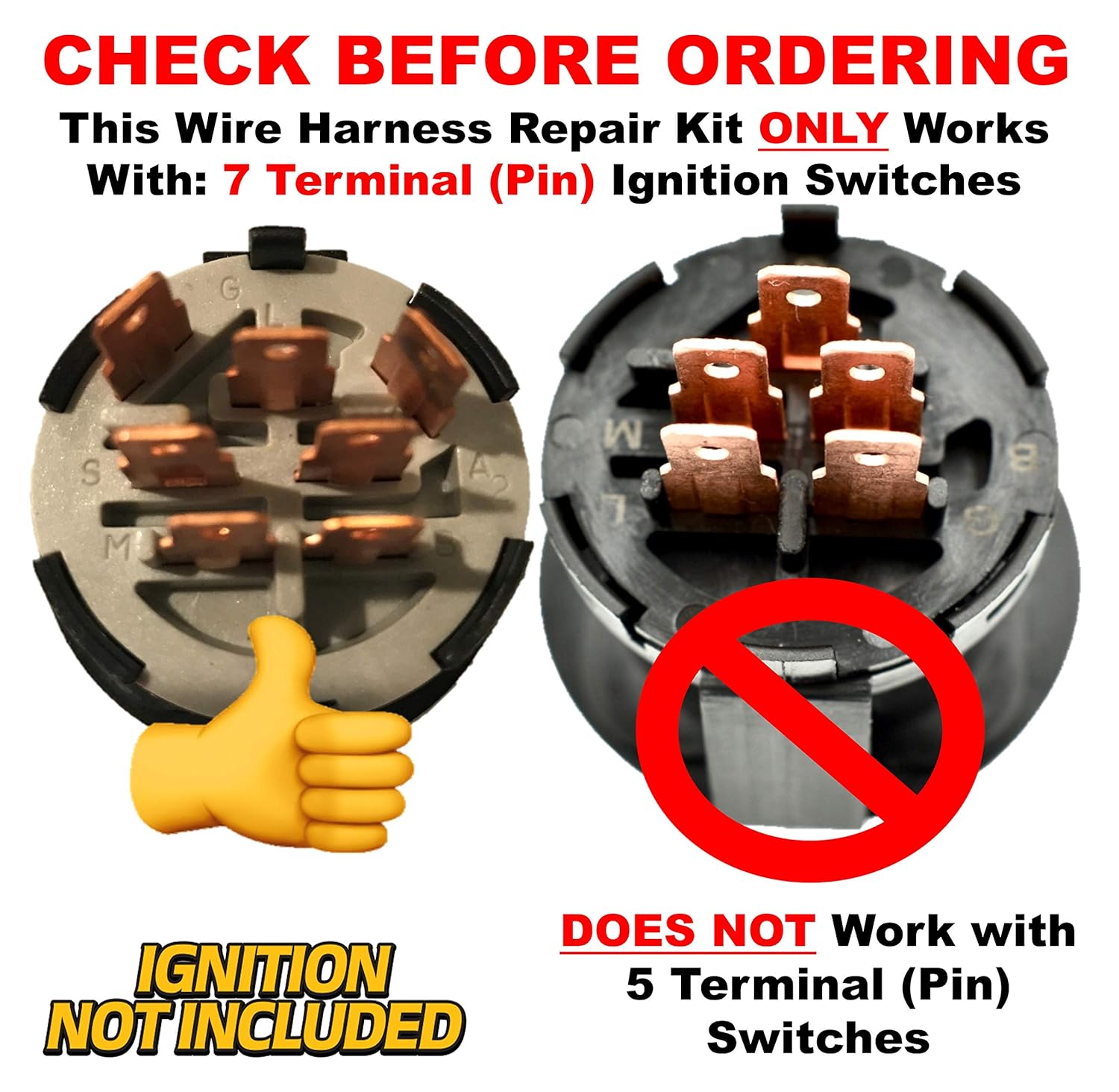
Image: Examples of compatible 7-terminal (pin) ignition switches. This kit is designed for these.
Important: Always visually inspect your current ignition switch and its terminal configuration to confirm compatibility before proceeding with installation.
3. Package Contents
Upon opening the package, ensure all the following components are present:
- 1x Ignition Switch Wire Harness with 7 crimped terminals and connector
- Multiple Butt Connectors (typically 5-7, depending on the specific kit)
- Corrugated Tubing (pre-installed on the harness)

Image: The HD Switch repair kit components, including the wire harness and butt connectors. Note: The ignition switch itself is not included.
4. Setup and Installation
Safety First: Before beginning any electrical work, ensure the equipment's battery is disconnected to prevent electrical shock or damage to the system.
- Access the Ignition Switch: Locate and access the existing ignition switch and its wire harness on your equipment. This may require removing dashboard panels or other covers.
- Inspect Existing Harness: Carefully examine the existing wire harness for damage, corrosion, or loose connections. Note the color coding and position of each wire connected to the ignition switch. It is highly recommended to take a photograph of the existing wiring before disconnection for reference.
- Disconnect Old Harness: Disconnect the old wire harness from the ignition switch. If the wires are individually connected, note their terminal positions.
- Prepare New Harness: The new HD Switch harness comes with pre-crimped terminals and a connector. You will need to cut the old wires from your equipment's main wiring loom, leaving enough length to connect to the new harness.
- Connect Wires: Using the provided butt connectors, connect each wire from your equipment's main wiring loom to the corresponding wire on the new HD Switch harness. Ensure that the wire colors match exactly. If wire colors do not match, refer to your equipment's specific wiring diagram. Crimp the butt connectors securely using an appropriate crimping tool.
- Secure Connections: After crimping, gently pull on each wire to ensure a secure connection. For added protection against moisture and corrosion, heat-shrink tubing can be applied over the butt connectors (not included).
- Connect to Ignition Switch: Plug the new HD Switch harness connector firmly into the 7-terminal, 4-position ignition switch.
- Test Functionality: Reconnect the equipment's battery. Test the ignition switch through all its positions (OFF, ACC, ON, START) to ensure proper operation of all connected systems (e.g., lights, engine start).
- Reassemble: Once functionality is confirmed, reassemble any panels or covers removed during the installation process.
Note: Professional installation is recommended if you are unfamiliar with electrical wiring or automotive repair.
5. Operating Instructions
This repair kit replaces the wire harness for your ignition switch. The operation of the ignition switch itself remains unchanged. Refer to your equipment's original owner's manual for specific operating instructions related to starting, stopping, and controlling your machinery.
Ensure the ignition switch is fully engaged in each position for proper function. Avoid forcing the key or switch.
6. Maintenance
Regular maintenance of your ignition switch wire harness can extend its lifespan and prevent future issues:
- Periodic Inspection: Annually inspect the wire harness and connections for signs of wear, fraying, corrosion, or loose terminals.
- Clean Connections: If corrosion is present, disconnect the battery and carefully clean the terminals and connector pins with a suitable electrical contact cleaner and a small brush.
- Secure Wiring: Ensure all wiring is properly routed and secured to prevent chafing or damage from vibration.
- Avoid Moisture: Keep the ignition switch area as dry as possible to prevent water ingress and corrosion.
7. Troubleshooting
If you experience issues after installing the new wire harness, consider the following troubleshooting steps:
| Problem | Possible Cause | Solution |
|---|---|---|
| Equipment does not start or power on. |
|
|
| Intermittent power or flickering lights. |
|
|
| Wires feel loose in the connector. |
|
|
If troubleshooting steps do not resolve the issue, consult a qualified technician or contact HD Switch customer support.
8. Specifications
- Brand: HD Switch
- Model Numbers: 12304, 04940800, 7035658YP
- Material: Plastic (connector and insulation)
- Connector Type: 7-Terminal (Pin)
- Compatibility: Designed for 4-Position Ignition Switches
- Kit Includes: Pre-wired harness, butt connectors, corrugated tubing
9. Warranty and Support
For specific warranty information regarding your HD Switch product, please refer to the documentation included with your purchase or visit the official HD Switch website. If you require technical assistance or have questions about installation, please contact HD Switch customer support directly.
Manufacturer: HD Switch
Contact: Refer to the official HD Switch website for current contact information.


