1. Introduction
This manual provides essential information for the installation, operation, and maintenance of the Comelit 1456G VIP Gateway Mini SIP. This device is designed to integrate SIP (Session Initiation Protocol) based communication into Comelit intercom systems, ensuring robust and reliable performance. Please read this manual thoroughly before installation and use to ensure proper functionality and safety.
2. Safety Information
Always observe the following safety precautions:
- Installation must be performed by qualified personnel in accordance with local electrical codes and regulations.
- Disconnect power before performing any installation, wiring, or maintenance procedures.
- Do not expose the device to moisture, rain, or extreme temperatures.
- Ensure proper grounding where required.
- Use only original Comelit accessories and spare parts.
3. Package Contents
Verify that all components are present in the package:
- Comelit 1456G VIP Gateway Mini SIP unit
- Installation hardware
4. Product Overview
The Comelit 1456G is a compact gateway designed for DIN rail mounting. It features various ports for power and network connections, facilitating the integration of SIP-based communication within a Comelit system.
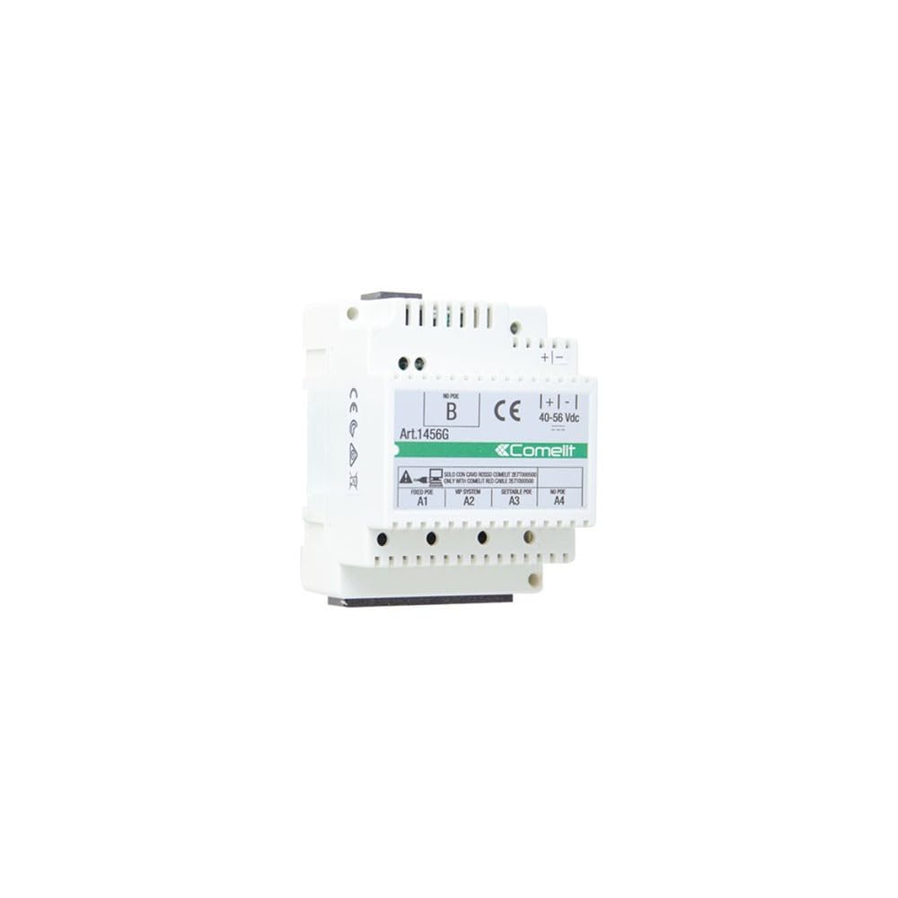
Image: Front view of the Comelit 1456G VIP Gateway Mini SIP. The unit is white with a green and white label indicating 'Art.1456G', 'Comelit', and various port labels such as 'FIXED POE A1', 'VIP SYSTEM A2', 'SETTABLE POE A3', 'NO POE A4'. Power input terminals are labeled '+|-' with a voltage range of '40-56 Vdc'.
Key indicators and connections include:
- Power Input: Terminals for 40-56 Vdc power supply.
- Network Ports: Labeled A1, A2, A3, A4, supporting various configurations including Fixed PoE, VIP System, Settable PoE, and No PoE connections.
- Status Indicators: (Not explicitly visible in image, but typical for such devices) LEDs for power, network activity, and system status.
5. Setup
5.1 Mounting
The 1456G unit is designed for installation on a standard DIN rail within an electrical enclosure or suitable mounting box. Ensure adequate ventilation around the unit.
5.2 Wiring
Before connecting any wires, ensure that the power supply is disconnected.
- Power Connection: Connect a stable 40-56 Vdc power supply to the designated '+|-' terminals. Observe polarity.
- Network Connections: Connect Ethernet cables from your network infrastructure and Comelit VIP system components to the appropriate A1-A4 ports as per your system design. Refer to your overall system diagram for specific port assignments (e.g., Fixed PoE, VIP System, Settable PoE, No PoE).
- Grounding: Ensure the unit is properly grounded if required by local regulations.
5.3 Initial Power-Up
Once all connections are secure, restore power to the unit. Observe the status indicators (if present) to confirm proper boot-up. The unit should initialize and connect to the network.
6. Operating
The Comelit 1456G VIP Gateway operates as an interface between SIP devices and the Comelit VIP intercom system. Its primary function is to facilitate communication and data exchange. Configuration of the gateway, including SIP account details and network settings, is typically performed via a web-based interface accessible through a connected computer on the same network. Refer to the Comelit VIP system documentation for detailed configuration procedures.
7. Maintenance
7.1 Cleaning
To clean the unit, disconnect power and use a soft, dry cloth. Do not use liquid cleaners or abrasive materials.
7.2 Firmware Updates
Periodically check the official Comelit website for firmware updates. Keeping the firmware up-to-date ensures optimal performance and access to the latest features and security enhancements. Follow the instructions provided with the firmware update package carefully.
8. Troubleshooting
If you encounter issues with your Comelit 1456G, consider the following:
- No Power: Check the power supply connection and ensure the 40-56 Vdc power source is active. Verify polarity.
- No Network Connectivity: Check Ethernet cable connections to all ports. Verify network settings and ensure the gateway has a valid IP address.
- SIP Communication Issues: Verify SIP account credentials and server settings in the gateway's configuration. Ensure network firewalls are not blocking SIP traffic.
- System Reset: If the unit is unresponsive, disconnect power for 30 seconds and then reconnect.
For persistent issues, consult the detailed troubleshooting guides available on the official Comelit support website or contact Comelit technical support.
9. Specifications
| Attribute | Value |
|---|---|
| Model Number | 1456G |
| Dimensions (L x W x H) | 56 x 26 x 23 cm |
| Weight | 600 g |
| Power Supply | 40-56 Vdc |
| Operating Temperature | Refer to manufacturer's datasheet |
| Mounting | DIN Rail |
10. Warranty and Support
For specific warranty terms and conditions, please refer to the warranty card included with your product or visit the official Comelit website. Technical support and service information can also be found on the Comelit website or by contacting your authorized Comelit distributor.


