
1. Product Overview
The Kolink KLM-003 is a compact Micro-Tower computer case designed to house Micro ATX motherboards and essential PC components. It features a durable alloy steel construction and is optimized for air cooling. This manual provides detailed instructions for assembly, operation, and maintenance.

Figure 1: Front-left view of the Kolink KLM-003 Micro-Tower Case, showcasing its minimalist design and front panel ventilation.

Figure 2: Multiple views of the Kolink KLM-003 case, illustrating the front panel, rear panel with I/O cutouts, and top panel layout.
2. Package Contents
Verify that all items are present in the package before proceeding with installation.
- Kolink KLM-003 Micro-Tower Case (1 unit)
- Accessory kit (screws, standoffs, cable ties)
- User Manual (This document)
3. Setup and Installation
This section guides you through the process of installing your computer components into the Kolink KLM-003 case. Ensure your workspace is clean and static-free. It is recommended to wear an anti-static wrist strap during installation.
3.1 Opening the Case
- Place the case on a flat, stable surface.
- Locate the thumbscrews on the rear panel of the case.
- Unscrew the thumbscrews and carefully slide off the side panel(s).

Figure 3: Interior view of the case with the side panel removed, showing the motherboard tray and internal layout.
3.2 Motherboard Installation
The KLM-003 supports Micro ATX motherboards.
- Install the I/O shield provided with your motherboard into the cutout on the rear of the case.
- Align your Micro ATX motherboard with the pre-installed standoffs inside the case.
- Secure the motherboard using the appropriate screws from the accessory kit.
3.3 Power Supply Installation
The power supply mounts at the rear of the case.
- Position your ATX power supply in the designated area at the rear of the case.
- Secure it with screws from the accessory kit, ensuring the fan faces the correct direction for optimal airflow (usually downwards or outwards).
3.4 Drive Installation (HDD/SSD)
The case provides bays for storage drives.
- Identify the 3.5-inch and 2.5-inch drive bays.
- Slide your hard drives (HDDs) or solid-state drives (SSDs) into the appropriate bays.
- Secure the drives using screws.

Figure 4: Close-up of the interior, highlighting the drive mounting areas and cable routing options.
3.5 Front Panel Connections
Connect the front panel cables to your motherboard. Refer to your motherboard manual for exact pin layouts.
- Power Button: Connect the "POWER SW" cable.
- Reset Button: Connect the "RESET SW" cable.
- Power LED: Connect the "POWER LED" cables (+/-).
- HDD LED: Connect the "HDD LED" cable.
- USB 2.0: Connect the USB 2.0 header cable.
- USB 3.0: Connect the USB 3.0 header cable (if available on case and motherboard).
- Audio: Connect the "HD AUDIO" cable.
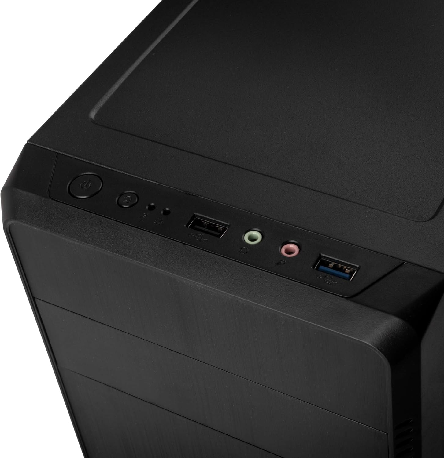
Figure 5: Top front panel with power button, reset button, USB 2.0, USB 3.0, and audio ports for easy access.
4. Operating Instructions
Once all components are installed and connected, you can power on your system.
- Ensure all cables are securely connected, both internally and externally (monitor, keyboard, mouse, power cord).
- Connect the power cord to the power supply unit and a wall outlet.
- Press the power button located on the front panel of the case.
- The power LED should illuminate, and your system should begin to boot.
5. Maintenance
Regular maintenance helps ensure optimal performance and longevity of your computer components.
- Dust Cleaning: Periodically clean dust from inside the case, especially from fans and heatsinks, using compressed air or a soft brush. Ensure the system is powered off and unplugged before cleaning.
- Exterior Cleaning: Wipe the exterior of the case with a soft, damp cloth. Avoid harsh chemicals or abrasive cleaners.
- Airflow: Ensure adequate airflow around the case. Do not block ventilation openings.
6. Troubleshooting
If you encounter issues, consider the following common troubleshooting steps:
- System Not Powering On:
- Check if the power cord is securely connected to both the power supply and the wall outlet.
- Ensure the power switch on the power supply unit is in the "ON" position.
- Verify that the front panel power button cable is correctly connected to the motherboard.
- No Display Output:
- Ensure your monitor is connected to the correct video output port on your graphics card or motherboard.
- Check that the graphics card is properly seated in its PCIe slot and has all necessary power cables connected.
- Overheating:
- Ensure all case fans and CPU cooler fans are spinning correctly.
- Clean any dust buildup from fans and heatsinks.
- Verify that the case has sufficient ventilation.
7. Specifications
| Model Name | KLM-003 |
| Brand | KOLINK |
| Case Type | Micro-Tower |
| Motherboard Compatibility | Micro ATX |
| Material | Alloy Steel |
| Color | Black |
| Dimensions (LxWxH) | 14.37 x 7.24 x 13.58 inches (36.5 x 18.4 x 34.5 cm) |
| Item Weight | 5.7 pounds (2.59 kg) |
| Cooling Method | Air |
| Fan Size (Rear) | 80 Millimeters (if included/supported) |
| Front I/O Ports | 1x USB 2.0, Audio In/Out, 1x USB 3.0 |
| Power Supply Mounting | Rear Mount |
Note: Specifications are subject to change without prior notice.
8. Safety Information
- Always disconnect the power cord from the wall outlet before opening the case or performing any maintenance.
- Avoid exposing the case to extreme temperatures, humidity, or direct sunlight.
- Keep the case away from liquids and sources of heat.
- Handle internal components with care to prevent damage from electrostatic discharge. Use an anti-static wrist strap if possible.
- Do not attempt to modify the case in ways not described in this manual.
9. Warranty and Support
For warranty information and technical support, please refer to the official KOLINK website or contact your retailer. Keep your proof of purchase for warranty claims.
KOLINK Official Website: www.kolink.eu


