
RS PRO RSDS 1052 DL+
RS PRO RSDS 1052 DL+ Digital Storage Oscilloscope User Manual
Model: RSDS 1052 DL+
1. Introduction
This manual provides comprehensive instructions for the safe and effective operation, maintenance, and troubleshooting of the RS PRO RSDS 1052 DL+ Digital Storage Oscilloscope. Please read this manual thoroughly before using the device to ensure proper functionality and to prevent damage or injury.
The RS PRO RSDS 1052 DL+ is a versatile 2-channel digital storage oscilloscope with a 50 MHz bandwidth, designed for precise signal analysis. It features a 7-inch TFT LCD display for clear waveform visualization and supports various measurement parameters and mathematical operations.
2. Safety Information
Always adhere to the following safety precautions to prevent electric shock, fire, or damage to the instrument.
- Power Source: Ensure the oscilloscope is connected to a power source within the specified voltage range (100-240V AC, 50/60Hz).
- Grounding: The instrument must be properly grounded to prevent electric shock. Do not defeat the grounding plug.
- Environment: Operate the oscilloscope in a dry, well-ventilated area, away from direct sunlight, high temperatures, and excessive dust.
- Probes: Use only probes supplied or recommended by RS PRO. Ensure probes are correctly rated for the voltage being measured.
- Maintenance: Refer all servicing to qualified service personnel. Do not attempt to open the instrument casing unless explicitly instructed.
- Safety Category: This device is rated CAT I, CAT II. Observe all safety warnings on the device and in this manual.
3. Product Overview and Components
This section provides an overview of the RS PRO RSDS 1052 DL+ oscilloscope and its main components.
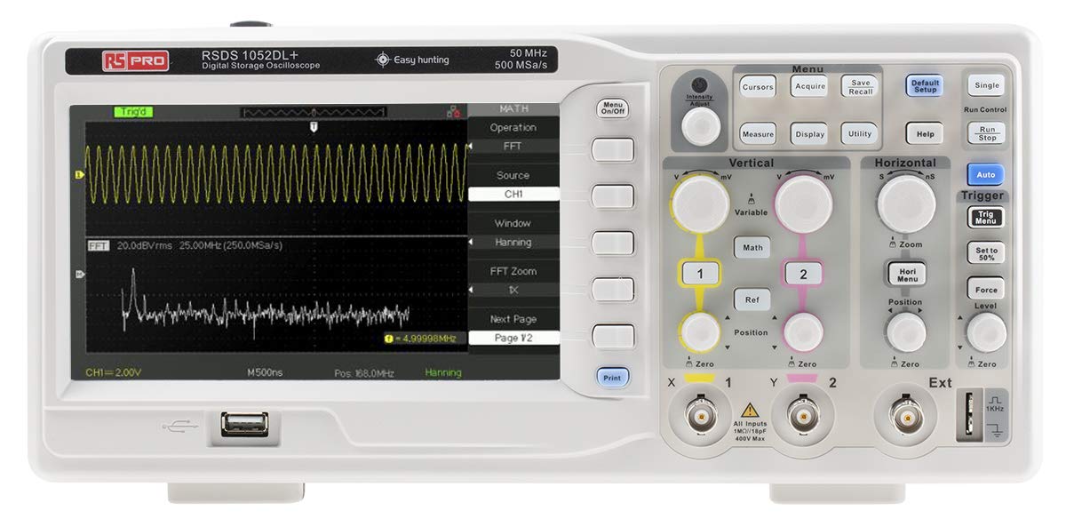
Figure 3.1: Front View of the Oscilloscope. This image shows the front panel of the RS PRO RSDS 1052 DL+ oscilloscope, highlighting the 7-inch TFT LCD display, control knobs, function buttons, and input connectors for channels 1 and 2. The screen displays a typical waveform and FFT analysis.

Figure 3.2: Angled View of the Oscilloscope. This image provides an angled perspective of the RS PRO RSDS 1052 DL+ oscilloscope, showcasing its compact design and integrated handle for portability. The side ventilation grilles are also visible.

Figure 3.3: Rear View of the Oscilloscope. This image displays the rear panel of the RS PRO RSDS 1052 DL+ oscilloscope, featuring the power input, USB device port, USB host port, LAN port, and Pass/Fail output. Safety warnings and product labels are also visible.
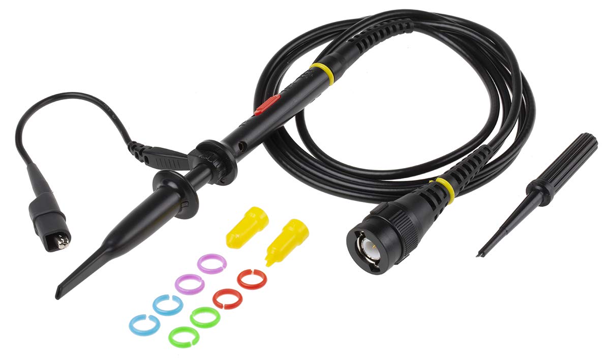
Figure 3.4: Oscilloscope Probe and Accessories. This image shows a passive oscilloscope probe (1:1/10:1) along with various accessories, including colored rings for channel identification and probe tip covers. These are essential for connecting signals to the oscilloscope.

Figure 3.5: Power Plugs and Probe Tip. This image displays an assortment of power plugs (EU, UK, US types) that may be included with the oscilloscope, along with a specialized probe tip. These ensure compatibility with various power outlets and provide versatility for measurements.
3.1 Included Accessories
The RS PRO RSDS 1052 DL+ typically includes the following accessories:
- Passive Probe 1:1/10:1 (x2)
- USB Cable
- Quick Start Guide
- Quality Certificate
- Power Cord (region-specific)
- CD (including User Manual and EasyScopeX software)
4. Setup
4.1 Unpacking and Inspection
- Carefully remove the oscilloscope and all accessories from the packaging.
- Inspect the instrument for any signs of physical damage during transit. If damage is found, contact your supplier immediately.
- Verify that all included accessories listed in Section 3.1 are present.
4.2 Power Connection
- Ensure the power switch on the rear panel is in the OFF position.
- Connect the provided power cord to the AC input on the rear panel of the oscilloscope.
- Plug the other end of the power cord into a grounded AC power outlet. The oscilloscope supports 100-240V AC, 50/60Hz.
4.3 Probe Connection and Compensation
- Connect the BNC connector of the passive probe to one of the input channels (CH1 or CH2) on the front panel.
- Attach the probe tip to the probe compensation output (usually a square wave test signal) on the front panel.
- Adjust the compensation trimmer on the probe until the displayed square wave is flat-topped, without overshoot or undershoot. This ensures accurate measurements.
5. Operating Instructions
5.1 Basic Operation
- Power On/Off: Press the power button on the front panel to turn the oscilloscope on or off.
- Auto Setup: Press the Auto button to automatically adjust vertical, horizontal, and trigger settings for a stable waveform display.
- Vertical Controls: Use the VOLTS/DIV knob to adjust the vertical scale (voltage per division) and the POSITION knob to move the waveform vertically.
- Horizontal Controls: Use the SEC/DIV knob to adjust the horizontal scale (time per division) and the POSITION knob to move the waveform horizontally.
- Trigger Controls: Adjust the LEVEL knob to set the trigger threshold. The trigger ensures a stable display of repetitive waveforms.
5.2 Advanced Functions
- Measurement Functions: Press the Measure button to access automatic measurement parameters such as Vpp, Vmax, Vmin, Freq, Period, etc.
- Math Functions: Press the Math button to perform mathematical operations on waveforms (e.g., Add, Subtract, Multiply, Divide, FFT).
- Storage and Recall: Use the Save/Recall buttons to save waveform data, setups, or screenshots to internal memory or a USB drive.
- USB Connectivity: Connect a USB drive to the front panel USB host port for data storage. Use the rear USB device port to connect the oscilloscope to a PC for data transfer and control via EasyScopeX software.
6. Maintenance
6.1 Cleaning
- Disconnect the power cord before cleaning.
- Use a soft, damp cloth with mild detergent to clean the exterior of the instrument.
- Do not use abrasive cleaners or solvents that may damage the plastic parts.
- Ensure no liquid enters the instrument.
6.2 Calibration
The oscilloscope is factory calibrated. For optimal performance, periodic calibration by qualified personnel is recommended, typically every 12-24 months, depending on usage and environmental conditions.
6.3 Storage
When not in use for extended periods, store the oscilloscope in a dry, dust-free environment, away from extreme temperatures and humidity.
7. Troubleshooting
This section provides solutions to common issues you might encounter.
| Problem | Possible Cause | Solution |
|---|---|---|
| No power | Power cord disconnected; Power switch off; Blown fuse | Check power cord connection; Turn power switch on; Contact service for fuse replacement. |
| No waveform displayed | Input signal too small/large; Incorrect vertical/horizontal settings; Trigger not set correctly; Probe not connected | Adjust VOLTS/DIV and SEC/DIV; Use Auto Setup; Adjust trigger level; Ensure probe is connected and compensated. |
| Unstable waveform | Incorrect trigger settings; No trigger source selected | Adjust trigger level and mode; Select appropriate trigger source (e.g., CH1, CH2, Ext). |
| Distorted waveform | Probe compensation incorrect; Probe damaged; Input overloaded | Perform probe compensation; Try a different probe; Check input signal amplitude. |
If the problem persists after attempting these solutions, please contact RS PRO customer support.
8. Specifications
Key technical specifications for the RS PRO RSDS 1052 DL+ Digital Storage Oscilloscope:
- Analog Channels: 2
- Oscilloscope Type: Digital Storage
- Bandwidth: 50 MHz
- Real-time Sample Rate: Up to 500 MSa/s
- Memory Depth: 32 Kpts
- Display Type: TFT LCD
- Display Size: 7 inches (800 x 480 pixels)
- Vertical Sensitivity: 2mV/div to 10V/div
- Time Base Range: 10ns/div to 50s/div
- Power Supply: Mains operated (100-240V AC, 50/60Hz)
- Weight: 2.5 kg
- Safety Category: CAT I, CAT II
- Interfaces: RS232, USB Host, USB Device, LAN
9. Warranty and Support
RS PRO products are manufactured to high standards and are typically covered by a manufacturer's warranty. Please refer to the warranty card included with your product or visit the official RS PRO website for detailed warranty terms and conditions.
For technical support, service, or inquiries regarding your RS PRO RSDS 1052 DL+ oscilloscope, please contact RS PRO customer service through their official channels. Contact information can usually be found on the RS PRO website or in the documentation provided with the product.
RS PRO Official Website: https://uk.rs-online.com/web/
Related documentsRSDS 1052 DL+


Ask a question about this manual
Ask about setup, troubleshooting, compatibility, parts, safety, or missing instructions. Manuals+ will review the question and use this page’s manual context to help answer it.