
1. Introduction
The Flysky FS-CPD02 is an optical RPM (Revolutions Per Minute) telemetry module designed for use with compatible Flysky RC systems. This module allows users to monitor the rotational speed of a motor or propeller in real-time, providing valuable data for optimizing performance and ensuring safe operation of remote-controlled models. It utilizes photo induction (optical) technology to detect RPM.
2. Safety Information
- Always ensure proper wiring and connections to avoid short circuits or damage to the module and other components.
- Operate within the specified voltage range (4.0-6.5V DC) to prevent malfunction or permanent damage.
- Keep the module away from moisture, extreme temperatures, and strong electromagnetic interference.
- Ensure the optical sensor is clean and unobstructed for accurate readings.
- This product is recommended for users aged 15 years and up.
3. Package Contents
Verify that your package contains the following items:
- 1x Flysky FS-CPD02 Optical RPM Telemetry Module
- Connection Cables
4. Product Overview
The FS-CPD02 module is a compact unit designed for easy integration into your RC model. It features an optical sensor for non-contact RPM measurement and connects to your Flysky receiver via an iBus port or similar telemetry input.
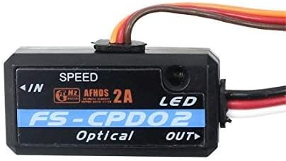
Image 1: Front view of the Flysky FS-CPD02 Optical RPM Telemetry Module, showing the 'SPEED' label, 'FS-CPD02 Optical' branding, and 'IN'/'OUT' ports. This image displays the compact black casing with a multi-colored wire harness extending from one side.
Key features include:
- Optical RPM Sensing: Utilizes photo induction for accurate, non-contact speed measurement.
- Wide RPM Range: Monitors speeds up to 60,000 RPM/mins.
- Compact Design: Small and lightweight for minimal impact on model performance.
- Telemetry Integration: Compatible with Flysky iBus telemetry systems for real-time data display on your transmitter.
5. Setup and Installation
Follow these steps to properly install and connect your FS-CPD02 module:
- Connect to Receiver: Connect the module's output cable to a compatible telemetry port on your Flysky receiver. The FS-CPD02 is directly compatible with iA4B and iA6B receivers. For iA10 receivers, a conversion cable may be required. Ensure the polarity is correct.
- Mount the Module: Securely mount the FS-CPD02 module within your model using double-sided tape or a suitable mounting method. Ensure it is protected from vibrations and potential impact.
- Position the Optical Sensor: The optical sensor (located on the module) needs a clear line of sight to a rotating part of your model, such as a propeller blade or a marked section of a motor shaft. For accurate readings, ensure there is a distinct contrast (e.g., a black mark on a white surface, or vice-versa) on the rotating part that the sensor can detect. The sensor should be positioned close enough to reliably detect the mark without interfering with the rotating component.
- Power Connection: The module draws power directly from the receiver, operating within the 4.0-6.5V DC range. No separate power supply is typically needed if your receiver provides adequate power.
- Transmitter Setup: Power on your Flysky transmitter (e.g., FS-i6, i10, iT4S) and navigate to the telemetry settings. Ensure the FS-CPD02 module is recognized and enabled. You may need to perform a sensor discovery function on your transmitter.

Image 2: The FS-CPD02 module shown with its attached multi-colored wiring harness, featuring a standard servo-style connector at the end. This illustrates the module's compact size and its primary connection interface.

Image 3: A top-down view of the FS-CPD02 module and its wiring. This image highlights the module's small form factor and the various connectors, including the main power/data connector and a smaller auxiliary connector, indicating its integration capabilities.

Image 4: The reverse side of the FS-CPD02 module, revealing its mounting screws and the entry point for the wiring harness. This view emphasizes the module's construction and how the wires are securely attached.

Image 5: A comprehensive view of the FS-CPD02 module with its entire length of connection cables laid out. This image provides a clear perspective on the cable length and the various connectors, aiding in understanding its installation requirements.
6. Operating Instructions
Once installed and configured, the FS-CPD02 module will transmit RPM data to your compatible Flysky transmitter. Refer to your transmitter's instruction manual for specific details on how to display telemetry data.
- Power On: Turn on your transmitter, then your model (receiver).
- Access Telemetry: On your transmitter, navigate to the telemetry display screen. You should see the RPM data from the FS-CPD02 module.
- Monitor RPM: As the motor or propeller rotates, the RPM value will update in real-time.
7. Maintenance
- Keep Clean: Regularly inspect the optical sensor for dust, dirt, or obstructions. Clean gently with a soft, dry cloth if necessary.
- Check Connections: Periodically verify that all connections are secure and free from corrosion.
- Storage: Store the module in a dry, cool environment when not in use.
8. Troubleshooting
- No RPM Data Displayed:
- Ensure the module is correctly connected to the receiver's telemetry port.
- Verify that the receiver is compatible and properly bound to the transmitter.
- Perform a sensor discovery on your transmitter.
- Check the optical sensor's alignment and ensure the rotating part has a clear, contrasting mark.
- Confirm the module is receiving power (4.0-6.5V DC).
- Inaccurate RPM Readings:
- Clean the optical sensor.
- Adjust the sensor's position relative to the rotating part for optimal detection.
- Ensure the contrasting mark on the rotating part is clear and consistent.
- Check for strong ambient light or reflections that might interfere with the optical sensor.
- Module Not Powering On:
- Check all power connections and ensure they are secure and correctly polarized.
- Verify that the receiver is providing power within the specified voltage range.
9. Specifications
| Feature | Specification |
|---|---|
| Model | FS-CPD02 |
| Type | RPM Telemetry Module (Photo Induction/Optical) |
| Monitor Range of Speed | 60,000 RPM/mins |
| Power Input | 4.0-6.5V DC |
| Weight | 6.8g |
| Dimensions | 31mm x 15mm x 8.5mm |
| Compatible Receivers | iA4B (directly), iA6B (directly), iA10 (with conversion cable) |
| Compatible Transmitters | FS-i6, FS-i10, FS-iT4S, and other telemetry-capable Flysky transmitters |
10. Warranty and Support
Flysky products are designed for reliability and performance. For warranty information, please refer to the documentation provided with your original purchase or visit the official Flysky website. For technical support, contact Flysky customer service through their official channels.


