1. Introduction
This instruction manual provides detailed information for the OONO 4 SPDT 10Amp Power Relay Module, DC 5V version. It covers product overview, features, setup, operating instructions, specifications, troubleshooting, and maintenance. This module is designed for integration into various electronic projects, including Raspberry Pi and other IoT applications, offering reliable control for higher power loads.
2. Product Overview
The OONO 4 SPDT 10Amp Power Relay Module is a compact and robust device featuring four Single Pole Double Throw (SPDT) relays, each capable of switching up to 10 Amperes. It is housed in an ABS plastic enclosure, providing protection and ease of mounting. The module is designed for DC 5V operation and includes LED indicators for power and relay status, along with high-quality screw terminal blocks for secure wiring.

Figure 2.1: Top view of the OONO 4 SPDT 10Amp Power Relay Module. This image displays the module's top surface, clearly showing the four sets of SPDT relay terminals (NC1, C1, NO1 to NC4, C4, NO4) at the top, and the power and input control terminals (PWR, DCIN, GND, IN-1 to IN-4) at the bottom. Four red LED indicators are visible, corresponding to each relay's status. The OONO brand and model number F-1002 are also printed on the module.
3. Features
- 4 Channel SPDT Relays: Equipped with four Single Pole Double Throw 10 Ampere power relays, suitable for various switching applications.
- Wide Application: Easily integrates with Raspberry Pi, other IoT projects, and home automation control systems.
- Efficient Drive Circuitry: Utilizes Darlington transistor circuits to drive relay coils, ensuring reliable operation.
- Status Indicators: Features LED indicators for power supply status and individual relay activation.
- Durable Enclosure: Housed in an ABS plastic enclosure, offering protection and options for screw mounting on surfaces or desktop placement.
- High-Quality Terminals: Includes high-quality screw terminal blocks with a pitch of 5.0mm/0.197", accommodating wire ranges from 26AWG to 12AWG (2.5mm²).
- Operating Voltage: Designed for DC 5V operation with a current consumption of approximately 300mA.
4. Setup
4.1 Component Identification
Familiarize yourself with the module's components and terminal labels before proceeding with wiring.

Figure 4.1: Angled view of the relay module. This image provides a perspective view of the module, emphasizing the screw terminal blocks for both input control and relay outputs. The robust design of the enclosure and the clear labeling of each terminal are visible.
4.2 Wiring Instructions
Refer to the schematic diagram for detailed internal connections. Ensure all power is disconnected before making any wiring changes.

Figure 4.2: Schematic diagram of the OONO 4 SPDT 10Amp Power Relay Module. This diagram illustrates the internal circuitry, including the power supply section (DCIN, GND), the control circuit unit for each channel (IN-1 to IN-4), and the corresponding SPDT relay outputs (NCx, Cx, NOx). It shows the Darlington transistor drive and LED indicators for each relay.
- Power Supply Connection:
- Connect the DCIN terminal to the positive (+) 5V DC power source.
- Connect the GND terminals to the negative (-) / ground of the 5V DC power source.
- Ensure the power supply is stable and provides the specified 5V DC.
- Control Input Connections:
- The module has four input terminals: IN-1, IN-2, IN-3, IN-4.
- These inputs are active-high. A logic HIGH signal (e.g., 3.3V or 5V from a microcontroller like Raspberry Pi) applied to an IN-x terminal will activate the corresponding relay.
- Connect the control pins from your microcontroller or control circuit to these IN-x terminals.
- Relay Output Connections:
- Each relay channel (1-4) provides three terminals: NCx (Normally Closed), Cx (Common), and NOx (Normally Open).
- When the relay is de-energized (IN-x is LOW), Cx is connected to NCx.
- When the relay is energized (IN-x is HIGH), Cx is connected to NOx.
- Connect the load you wish to control to the appropriate terminals (Cx and either NCx or NOx) based on your application's requirements.
- Ensure the load's voltage and current do not exceed the relay's maximum ratings (10A).
4.3 Mounting
The ABS plastic enclosure is designed for versatile mounting. It can be placed on a desktop or securely mounted to a wood board or wall using screws through the integrated mounting tabs.
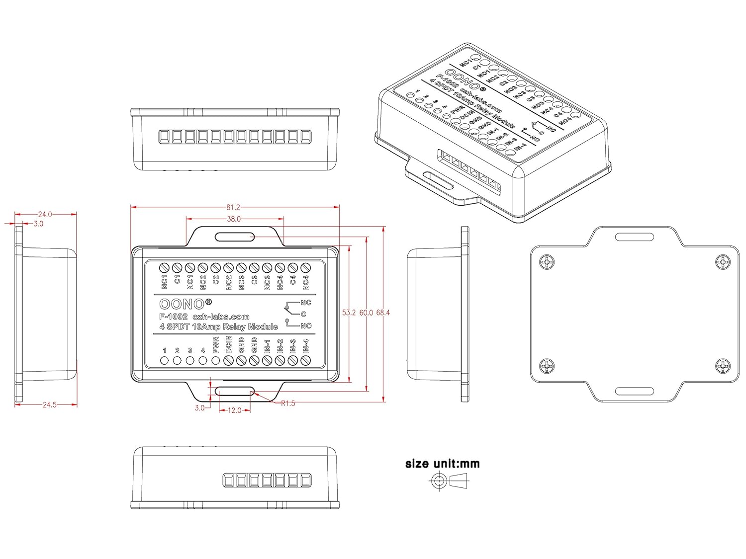
Figure 4.3: Dimensional drawing of the relay module. This technical drawing provides precise measurements in millimeters for the module's length, width, height, and the spacing of its mounting holes. It includes top, side, and isometric views, which are essential for planning installation and enclosure integration.
5. Operating Instructions
Once the module is correctly wired and powered, control is achieved by applying logic signals to the IN-x terminals.
- Power Indicator: The PWR LED will illuminate when the module receives a stable 5V DC power supply.
- Relay Status Indicators: Each relay has a corresponding red LED (labeled 1, 2, 3, 4). When a logic HIGH signal is applied to an IN-x terminal, the respective relay will energize, and its LED will illuminate. This indicates that the Common (Cx) terminal is now connected to the Normally Open (NOx) terminal.
- De-energizing Relays: When the logic signal on an IN-x terminal is removed (set to LOW), the relay will de-energize, and its LED will turn off. The Common (Cx) terminal will then revert to being connected to the Normally Closed (NCx) terminal.
Always ensure that the control signals from your microcontroller are within the compatible voltage range (typically 3.3V or 5V for logic HIGH) to avoid damage to the module or the controlling device.
6. Specifications
| Feature | Specification |
|---|---|
| Model Number | MD-F1002/5V-1 |
| Number of Channels | 4 |
| Relay Type | SPDT (Single Pole Double Throw) |
| Current Rating (per relay) | 10 Amps |
| Operating Voltage | DC 5V |
| Operating Current | 300mA (approx.) |
| Control Input Type | Active-High Logic |
| Connector Type | Screw Terminal Block |
| Terminal Pitch | 5.0mm / 0.197" |
| Wire Range | 26AWG ~ 12AWG / 2.5mm² |
| Enclosure Material | ABS Plastic |
| Mounting Type | Screw Mount |
| Contact Material | Silver |
| Dimensions | 3.8 x 3.4 x 1.4 inches (approx.) |
| Weight | 4.8 ounces (approx.) |
7. Troubleshooting
- Relay Not Activating:
- Check if the 5V DC power supply is correctly connected to DCIN and GND terminals and is stable. The PWR LED should be on.
- Verify that a logic HIGH signal is being applied to the correct IN-x terminal.
- Ensure the control signal voltage is sufficient (e.g., 3.3V or 5V).
- Inspect wiring for loose connections or incorrect polarity.
- Load Not Switching:
- Confirm the relay LED illuminates when the control signal is applied.
- Check the wiring of the load to the Cx, NCx, or NOx terminals.
- Ensure the load's voltage and current requirements do not exceed the relay's 10A rating. Overloaded relays may fail to switch or sustain damage.
- Test the load independently to ensure it is functional.
- Module Overheating:
- Verify that the current drawn by the loads connected to the relays does not exceed the 10A per channel rating.
- Ensure adequate ventilation around the module, especially if operating near maximum load.
8. Maintenance
The OONO 4 SPDT 10Amp Power Relay Module is designed for reliable, low-maintenance operation. Follow these guidelines for optimal performance:
- Cleaning: Keep the module clean and free from dust and debris. Use a soft, dry cloth for cleaning. Avoid using liquids or abrasive cleaners.
- Environment: Operate the module in a dry environment, away from excessive moisture, extreme temperatures, and corrosive substances.
- Connections: Periodically check all screw terminal connections to ensure they remain tight and secure. Loose connections can lead to intermittent operation or overheating.
- Inspection: Visually inspect the module for any signs of damage, such as cracked casing or burnt components. If damage is observed, discontinue use.
9. Warranty & Support
For warranty information and technical support, please refer to the OONO official website or contact your retailer. Keep your purchase receipt for any warranty claims.
For further assistance, you may contact OONO customer support via their official channels. Please provide your product model number (MD-F1002/5V-1) and a detailed description of the issue when seeking support.


