
1. Introduction
The OWON HDS1021MN is a versatile handheld device combining the functionalities of a digital storage oscilloscope and a digital multimeter. It is designed for engineers, technicians, and hobbyists requiring portable and accurate measurement capabilities. This manual provides essential information for the safe and effective operation of your device.
Key Features:
- Model: HDS1021MN
- Sample Rate (real time): 500MS/s
- Bandwidth: 20MHz
- Horizontal Scale (s/div): 5ns/div to 100s/div, step by 1-2.5-5
- Channel: Single
- Waveform Record & Replay
- FFT Functions
- 3.7 inch color TFT display (640 × 480 pixels)
2. Safety Information
Before using the OWON HDS1021MN, please read and understand all safety instructions. Failure to follow these instructions may result in electric shock, fire, or damage to the device or other equipment.
- General Safety: Always operate the device within its specified voltage and current limits. Do not use the device if it appears damaged or is not operating correctly.
- Power Supply: Use only the specified power adapter and battery. Ensure the power source matches the device's requirements.
- Probes and Leads: Use only probes and test leads rated for the voltage and current being measured. Inspect probes and leads for damage before each use.
- Environment: Do not operate the device in wet or damp conditions, or in explosive atmospheres. Keep the device away from strong electromagnetic fields.
- Servicing: Refer all servicing to qualified service personnel. Do not attempt to open or repair the device yourself.
3. Product Components
The standard package for the OWON HDS1021MN typically includes the following items:
- OWON HDS1021MN Handheld Digital Storage Oscilloscope and Digital Multimeter Unit
- Oscilloscope Probe (1X/10X)
- Multimeter Test Leads
- Power Adapter
- USB Cable
- User Manual (this document)
- Soft Carrying Case (may vary by region/retailer)
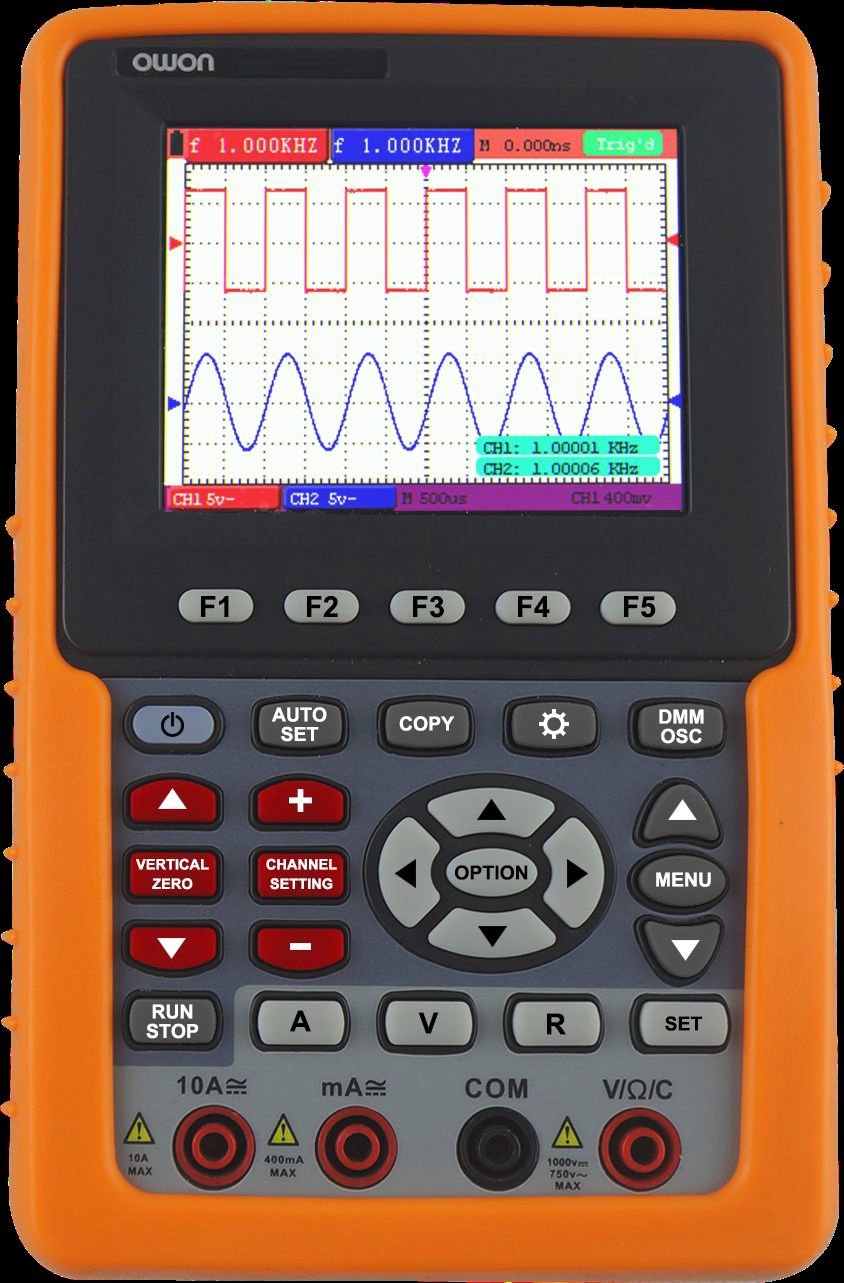
Front view of the OWON HDS1021MN, showing the display screen, control buttons, and input jacks.
4. Setup
4.1 Battery Installation and Charging
- Locate the battery compartment on the rear of the device.
- Insert the provided Li-ion battery (7.4V) into the compartment, ensuring correct polarity.
- Close the battery compartment cover securely.
- Connect the power adapter to the device's charging port and plug it into a suitable AC outlet (100V-240V AC, 50/60Hz). The battery indicator will show charging status.
- Allow the device to charge fully before initial use. A full charge provides approximately 6 hours of operation.
4.2 Connecting Probes and Test Leads
- Oscilloscope Probe: For oscilloscope functions, connect the BNC connector of the oscilloscope probe to the BNC input port on the device. Ensure the probe's attenuation setting (e.g., 1X or 10X) matches the setting on the oscilloscope menu.
- Multimeter Test Leads: For multimeter functions, insert the red test lead into the VΩmA input jack and the black test lead into the COM input jack. For high current measurements (e.g., 20A), use the dedicated current input jack if available and switch the function accordingly.
5. Operating Instructions
5.1 Power On/Off
Press and hold the power button until the display illuminates to turn on the device. To power off, press and hold the power button again until the display shuts down.
5.2 Oscilloscope Operation
- Select Oscilloscope Mode: Use the function selection buttons to switch to oscilloscope mode.
- Connect Probe: Attach the oscilloscope probe to the circuit under test. Ensure the ground clip is connected to the circuit's ground.
- Adjust Vertical Scale (Volts/Div): Use the vertical control knob or buttons to adjust the voltage sensitivity per division, matching the amplitude of the input signal.
- Adjust Horizontal Scale (Time/Div): Use the horizontal control knob or buttons to adjust the time base per division, suitable for viewing the signal's frequency.
- Set Trigger: Use the trigger controls to stabilize the waveform. Common trigger types include Edge, Video, and Alternate. Adjust the trigger level to a point on the waveform to ensure a stable display.
- Acquisition Mode: Select Sample, Peak Detect, or Average mode based on measurement needs.
- Waveform Record & Replay: Access the menu to enable waveform recording. Follow on-screen prompts to save and replay captured waveforms.
- FFT Function: Activate the FFT (Fast Fourier Transform) function from the menu to analyze the frequency components of the signal.
5.3 Multimeter Operation
- Select Multimeter Mode: Use the function selection buttons to switch to multimeter mode.
- Select Measurement Function: Rotate the rotary switch or press function buttons to select the desired measurement (e.g., VDC, VAC, Current DC, Current AC, Resistance, Diode, Continuity).
- Connect Test Leads: Connect the red and black test leads to the circuit or component being measured according to the selected function.
- Read Measurement: The measurement value will be displayed on the screen.
- Diode Test: Connect leads across the diode. The forward voltage drop will be displayed.
- Continuity Test: Connect leads across the circuit. An audible beep indicates continuity (<50Ω).
6. Maintenance
6.1 Cleaning
To clean the device, use a soft cloth dampened with mild detergent and water. Do not use abrasive cleaners or solvents. Ensure the device is powered off and disconnected from all power sources before cleaning.
6.2 Battery Care
- Charge the battery regularly, even if the device is not in frequent use, to maintain battery health.
- Avoid fully discharging the battery frequently.
- If storing the device for an extended period, charge the battery to approximately 50% and store in a cool, dry place.
6.3 Storage
Store the device in a dry, dust-free environment, away from direct sunlight and extreme temperatures. Use the provided carrying case to protect it from physical damage.
7. Troubleshooting
This section addresses common issues you might encounter with your OWON HDS1021MN.
| Problem | Possible Cause | Solution |
|---|---|---|
| Device does not power on | Low or dead battery; Power adapter not connected; Device fault | Charge the battery; Connect power adapter; Contact support if issue persists |
| No waveform displayed (Oscilloscope) | Probe not connected; Incorrect vertical/horizontal scale; Incorrect trigger settings; No input signal | Check probe connection; Adjust Volts/Div and Time/Div; Adjust trigger level/mode; Verify signal source |
| Incorrect multimeter reading | Incorrect function selected; Test leads improperly connected; Damaged test leads; Out of range measurement | Select correct function; Ensure leads are in correct jacks; Replace damaged leads; Check measurement range |
| Display is dim or flickering | Low battery; Environmental factors | Charge battery; Operate in recommended temperature range |
8. Specifications
Detailed technical specifications for the OWON HDS1021MN.
Oscilloscope Specifications:
- Bandwidth: 20MHz
- Sample Rate (real time): 500MS/s
- Horizontal Scale (s/div): 5ns/div to 100s/div, step by 1-2.5-5
- Rise Time (at input, typical): ≤ 17.5ns
- Display: 3.7 inch color TFT panel (640 × 480 pixels, 65535 colors)
- Channel: Single
- Input Impedance: 1MΩ ± 2%, in parallel with 20pF ± 5pF
- Record Length: max 6K points on each channel
- Interpolation: sin (x) / x
- Probe Attenuation Factor: 1X, 10X, 100X, 1000X
- Input Coupling: DC, AC, and GND
- DC Accuracy (average): average >16 : ±(5% reading + 0.05div) for ΔV
- Vertical Sensitivity: 5mV/div to 5V/div (at input)
- Vertical Resolution (A/D): 8 bits (2 channels simultaneously)
- Max Input Voltage: 400V (PK - PK) (DC + AC, PK - PK, 1MΩ input impedance, probe attenuation 10:1), CAT II
- Trigger Type: Edge, Video, Alternate
- Trigger Mode: Auto, Normal, Single
- Trigger Level: ±6 divisions from screen center
- Acquisition Mode: Sample, Peak Detect, and Average
- DC Gain Accuracy: ±3%
- Automatic Measurement: Vpp, Vavg, Vrms, Freq, Period, Vmax, Vmin, Vtop, Vbase, Vamp, Overshoot, Pre-shoot, Rise Time, Fall Time, +Width, -Width, +Duty, -Duty, Delay A→B, Delay A→B
- Waveform Math: +, -, ×, ÷, invert, FFT
- Waveform Storage: 4 waveforms
- Lissajous Figure: Bandwidth full bandwidth, Phase Difference ±3 degrees
Multimeter Specifications:
- Full Scale Reading: 3 ¾ digit (max 4000-count)
- Diode: 0V-1.5V
- Input Impedance: 10 MΩ
- On / Off Test: <50Ω (± 30Ω) beeping
- Voltage VDC: 400mV, 4V, 40V, 400V, 1000V : ±(1% ± 1 digit); max input : DC 1000V
- Voltage VAC: 4V, 40V, 400V : ±(1% ± 3 digits), 750V : ±(2% ± 3 digits); Frequency : 40Hz - 400Hz; max input : AC 750V (virtual value)
- Current DC: 40mA, 400mA : ±(1.5% ± 1 digit), 20A : ±(3% ± 3 digits)
- Current AC: 40mA : ±(1.5% ± 3 digits), 400mA : ±(2% ± 1 digit), 20A : ±(5% ± 3 digits)
General Specifications:
- Communication Interface: USB
- Power Supply: 100V-240V AC, 50/60Hz
- Li-ion Battery: 7.4V, 6 hours operation
- Dimensions (W × H × D): 180 × 115 × 40 (mm)
- Color: Orange
9. Warranty and Support
OWON products are manufactured to high quality standards. For warranty information, please refer to the warranty card included with your product or visit the official OWON website. For technical support, troubleshooting assistance beyond this manual, or service inquiries, please contact OWON customer support through their official channels.
Manufacturer: OWON


