1. Product Overview
The Walfront NiMH Battery Charger Board is a compact and efficient charging module designed for 1-cell (1S), 2-cell (2S), or 3-cell (3S) Nickel-Metal Hydride (NiMH) battery packs. This specific variant is configured for 2S operation and does not include pre-attached terminals, requiring direct soldering for connections. It features advanced charging capabilities to ensure safe and optimal battery performance.
Key Features:
- Thermal Regulation: Incorporates constant current / constant temperature operation with thermal regulation to maximize charging efficiency while preventing overheating.
- Automatic Low-Power Sleep Mode: Enters a low-power sleep mode automatically when the power input is removed, conserving energy.
- Precharge Regulation: Features precharge regulation for safely recovering deeply discharged batteries and minimizing heat dissipation during the initial charging phase.
- LED Indicator: Equipped with an LED indicator to display the charging status, allowing for easy monitoring.
- Maintenance Charging Mode: Includes a maintenance charging mode with timer termination for optimal battery longevity.
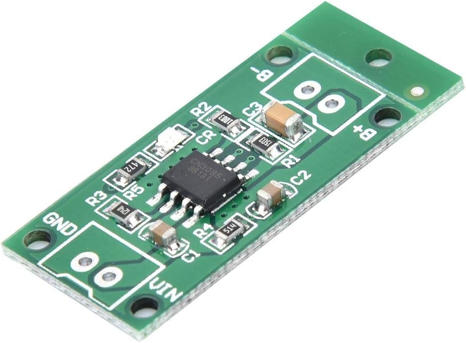
Figure 1: Top view of the Walfront NiMH Battery Charger Board, displaying the main integrated circuit (IC) and surface-mounted components. Key connection points for input voltage (VIN, GND) and battery terminals (B+, B-) are visible.
2. Specifications
Electrical Specifications:
| Parameter | 1-Cell (1S) Version | 2-Cell (2S) Version (Current Model) | 3-Cell (3S) Version |
|---|---|---|---|
| Input Voltage | 3.5V-6V (Recommended: 3.7V/3.8V/4.5V/5V) | 3.7V-6V (Recommended: 3.7V/3.8V/4.5V/5V) | 5V-6V (Recommended: 5V) |
| Charging Voltage | 1.5V | 3V | 4.5V |
| Charging Current | 1A | 1A | 1A |
| Operating Temperature | -40°C to 85°C | ||
| Storage Temperature | -65°C to 125°C | ||
Physical Specifications:
| Parameter | Value |
|---|---|
| Manufacturer | Walfront |
| Part Number | Walfrontgobc21wyin-12 |
| Product Dimensions | 30 x 15 x 2.7 mm (1.18 x 0.59 x 0.11 inches) |
| Item Weight | 1 Grams (0.035 ounces) |
| Material | Plastic (PCB) |
| Battery Cell Type | NiMH |
3. Setup and Installation
Careful attention to wiring is crucial for the correct and safe operation of the charger board. Incorrect connections can damage the board, batteries, or power supply.
3.1. Identifying Connection Points
The board features clearly labeled solder pads for power input and battery connection:
- VIN: Positive input voltage terminal.
- GND: Ground input voltage terminal.
- BAT+: Positive battery terminal.
- BAT-: Negative battery terminal.
3.2. Cell Count Selection (1S/2S/3S)
This charger board supports 1-cell, 2-cell, or 3-cell NiMH battery configurations. To select the appropriate cell count, you must bridge the corresponding solder pads on the bottom of the board. For this 2S variant, ensure the '2S' pads are bridged. If you intend to use a 1S or 3S battery pack, you must bridge the respective '1S' or '3S' pads instead. Only one set of pads (1S, 2S, or 3S) should be bridged at a time.

Figure 2: Bottom view of the charger board illustrating solder pads for battery (BAT+, BAT-) and power input (VIN, GND). The designated pads for selecting the battery cell count (1S, 2S, 3S) are also shown. Bridge the appropriate pads for your battery configuration.
3.3. Wiring Instructions
Important: Some diagrams found online or in product listings may incorrectly depict the input and output connections. Always connect the battery cells to the BAT+ and BAT- terminals, and the power input to the VIN and GND terminals.
- Prepare Wires: Use appropriate gauge wires for your application. While the board is small, ensure wires are securely soldered. You may need to slightly enlarge the mounting holes if using thicker wires (e.g., 22 gauge).
- Connect Battery: Solder the positive terminal of your NiMH battery pack to the BAT+ pad and the negative terminal to the BAT- pad.
- Connect Power Input: Solder the positive lead of your DC power supply (within the specified input voltage range for your selected cell count) to the VIN pad and the negative lead to the GND pad.
- Verify Connections: Double-check all solder joints for secure connections and correct polarity before applying power.
Warning: Incorrect polarity or bridging multiple cell selection pads can cause permanent damage to the charger board and connected batteries.
4. Operation
Once properly installed and wired, the charger board operates automatically to charge your NiMH battery pack.
4.1. Charging Process
- When power is applied to VIN and GND, the board will begin charging the connected NiMH battery pack.
- The charging process follows a constant current / constant temperature (CC/CT) method, optimized for NiMH batteries.
- For deeply discharged batteries, the board will initiate a precharge phase to safely bring the battery voltage up before full current charging.
4.2. LED Indicator
The board includes a small surface-mounted LED to indicate the charging status:
- Solid ON: Indicates that the battery is currently charging.
- OFF: Indicates that the battery is fully charged, or the power input has been removed.
- Blinking: May indicate an issue with the input voltage or battery connection. Refer to the Troubleshooting section.
4.3. Automatic Low-Power Sleep Mode
The charger board is designed to enter an automatic low-power sleep mode when the input power (VIN) is disconnected. This feature helps conserve energy when the charger is not actively powered.
4.4. Maintenance Charging
Upon completion of the main charging cycle, the board may enter a maintenance charging mode. This mode, often terminated by a timer, helps keep the battery at full capacity without overcharging, contributing to battery longevity.
5. Troubleshooting
If you encounter issues with your Walfront NiMH Battery Charger Board, refer to the following common problems and solutions:
| Problem | Possible Cause | Solution |
|---|---|---|
| LED is blinking or not solid ON during charging. | Input voltage is too high or unstable. | Verify that your input voltage (VIN) is within the specified range for your selected cell count (e.g., 3.7V-6V for 2S). Use a stable power supply. |
| Battery is not charging. | Incorrect wiring, no input power, or incorrect cell count selection. | Check all wiring connections (VIN, GND, BAT+, BAT-) for correct polarity and secure soldering. Ensure power is supplied to VIN/GND. Verify that the correct 1S/2S/3S pads are bridged for your battery pack. |
| Board or battery becomes excessively hot during charging. | Input voltage too high, short circuit, or faulty battery. | Immediately disconnect power. Check input voltage. Inspect wiring for any short circuits. Test the battery separately to ensure it is not faulty. Ensure adequate ventilation around the board. |
| LED is OFF, but battery is not fully charged. | No input power, or battery is deeply discharged and in precharge phase (LED might not be visible). | Ensure input power is connected. If the battery is deeply discharged, allow time for the precharge phase. If still no charge, check wiring and input voltage. |
6. Care and Maintenance
To ensure the longevity and reliable operation of your Walfront NiMH Battery Charger Board, follow these general care guidelines:
- Keep Dry: Protect the board from moisture and liquids, which can cause short circuits and corrosion.
- Avoid Physical Damage: Handle the board carefully to prevent bending, dropping, or other physical impacts that could damage components or solder joints.
- Cleanliness: Keep the board free from dust and debris. If cleaning is necessary, use a soft, dry brush or compressed air. Avoid using harsh chemicals.
- Proper Ventilation: Ensure the board is operated in an environment with adequate airflow to prevent heat buildup, especially during prolonged charging cycles.
- Storage: When not in use, store the board in a dry, cool environment, away from direct sunlight and extreme temperatures.
7. Warranty and Support
Information regarding specific warranty terms and direct customer support channels for the Walfront NiMH Battery Charger Board was not provided in the product data. For any support inquiries, please refer to the retailer or platform where the product was purchased.


