
Valefod VA-0189
Valefod DC-DC 5A Buck Converter (Model VA-0189) Instruction Manual
Model: VA-0189 | Brand: Valefod
1. Introduction
This manual provides detailed instructions for the Valefod DC-DC 5A Buck Converter, Model VA-0189. This module is designed to efficiently step down a higher DC input voltage to a lower, adjustable DC output voltage. It features a digital LED display for voltage monitoring and a potentiometer for precise output voltage adjustment.

Figure 1: Two Valefod DC-DC 5A Buck Converter modules.
2. Product Features
- High Precision Design: Features 36u thickened circuit boards, a high-Q inductance with an output LED indicator, and solid-state capacitors for effective high-frequency noise filtering.
- Input Voltage Range: DC 4V to 38V. Note: Input voltage must be at least 1.5V higher than the desired output voltage (no boost function).
- Output Voltage Range: Continuously adjustable from DC 1.25V to 36V.
- Maximum Output Current: 5 Amperes.
- Compact Size: Dimensions are 62mm x 38mm x 14mm (including potentiometer).
- Integrated LED Display: Digital voltmeter for monitoring input or output voltage.
- Adjustable Potentiometer: Allows for easy adjustment of the output voltage.
3. Important Safety Notes
- Voltage Differential: The input voltage must always be at least 1.5V higher than the output voltage. This module does not support voltage boosting.
- Polarity: Do not reverse the polarity of the input and output connections. Incorrect wiring can damage the module.
- Current/Power Limits: Keep the output current under 5A and the total power under 75W. For prolonged operation at higher loads, a heat sink is recommended to prevent overheating.
- Initial Adjustment: The factory setting for the output voltage may be high. It may be necessary to turn the blue potentiometer screw counter-clockwise approximately 7-15 full rotations before the output voltage begins to decrease.
4. Setup and Connections
Follow these steps to set up your Valefod DC-DC Buck Converter:
- Identify Terminals: Locate the "IN+" and "IN-" terminals for input, and "OUT+" and "OUT-" terminals for output.
- Input Connection: Connect your DC power source (4V-38V) to the "IN+" (positive) and "IN-" (negative) terminals. Ensure correct polarity.
- Output Connection: Connect your load or device to the "OUT+" (positive) and "OUT-" (negative) terminals. Ensure correct polarity.
- Initial Voltage Check: Before connecting a sensitive load, it is highly recommended to verify the output voltage using a multimeter.

Figure 2: Module layout with input/output connections and controls.

Figure 3: Detailed view of the buck converter components.
5. Operating Instructions
5.1. Adjusting Output Voltage
The output voltage is adjusted using the blue multi-turn potentiometer located on the module. A small screwdriver is required for this adjustment.
- Power On: Connect the input power source. The LED display will illuminate.
- Monitor Output: Use a multimeter to accurately measure the voltage across the "OUT+" and "OUT-" terminals. While the onboard LED display provides an indication, a multimeter offers higher precision for initial setup.
- Adjust Potentiometer:
- Turn the screw clockwise to increase the output voltage.
- Turn the screw counter-clockwise to decrease the output voltage.
- Initial Adjustment Note: As mentioned in the safety notes, the factory default voltage may be high. You might need to turn the potentiometer counter-clockwise for 7-15 full rotations before the voltage starts to drop. Each full rotation typically adjusts the voltage by approximately 1V.
- Fine-tuning: Adjust slowly until the desired output voltage is achieved on your multimeter.
5.2. Using the Digital Voltmeter
The module includes a digital LED display to show voltage readings. There are two buttons for controlling the display:
- Left Button ("ON/OFF"):
- Short Press: Turns the digital voltmeter ON.
- Long Press (1-4 seconds): Turns the digital voltmeter OFF.
- Right Button ("Mode"):
- Short Press: Toggles between displaying the input voltage (indicated by "IN" LED) and the output voltage (indicated by "OUT" LED).
6. Voltmeter Calibration (Optional)
For users requiring highly accurate voltage readings from the onboard digital display, the voltmeter can be calibrated. The calibration range is -0.5V to +0.5V, with a factory setting of 0.0V.
- Activate Voltmeter: Short press the left "ON/OFF" button to ensure the digital display is active.
- Enter Calibration Mode: Long press the left "ON/OFF" button for more than 4 seconds.
- The "IN" indicator LED will light up, signifying that input voltage measurement calibration has started.
- Adjust Input Voltage Calibration:
- Tap the left button to reduce the calibration value.
- Tap the right button to increase the calibration value.
- Since one unit of adjustment is less than 0.1V, you may need to tap the button 1-5 times continuously to observe a 0.1V change on the display.
- Switch to Output Voltage Calibration: After calibrating the input voltage, long press the right "Mode" button for more than 2 seconds.
- The "OUT" indicator LED will light up, signifying that output voltage measurement calibration has started.
- Adjust Output Voltage Calibration: Use the left and right buttons as described in step 3 to adjust the output voltage calibration value.
- Save and Exit: After completing both calibrations, long press the right "Mode" button for more than 2 seconds to save the adjusted values. The module will then return to normal voltage display mode. The calibrated values are retained even after power loss.
7. Maintenance
The Valefod DC-DC Buck Converter is designed for reliable operation with minimal maintenance. Observe the following guidelines:
- Cleanliness: Keep the module free from dust, dirt, and moisture. Use a soft, dry cloth for cleaning.
- Ventilation: Ensure adequate airflow around the module, especially when operating at higher currents or for extended periods. If necessary, attach the provided heat sink or ensure it is mounted in a well-ventilated enclosure.
- Connections: Periodically check all input and output connections to ensure they are secure and free from corrosion.
- Environmental Conditions: Operate the module within its specified temperature and humidity ranges to ensure optimal performance and longevity.

Figure 4: Module with included heatsink and mounting hardware.
8. Troubleshooting
If you encounter issues with your buck converter, consider the following troubleshooting steps:
- No Output Voltage / Display Off:
- Check input power supply: Ensure it is connected correctly and providing voltage within the 4V-38V range.
- Verify polarity: Confirm that input and output connections are not reversed.
- Check for short circuits: Inspect output connections for any short circuits that might trigger protection.
- Display ON/OFF: Short press the left button to ensure the digital display is turned on.
- Output Voltage Not Adjusting:
- Initial High Voltage: Remember that the factory setting might be high. Turn the potentiometer counter-clockwise for 7-15 full rotations to bring the voltage down into an adjustable range.
- Input Voltage Requirement: Ensure the input voltage is at least 1.5V higher than your target output voltage.
- Potentiometer Functionality: If after many turns the voltage still doesn't change, the potentiometer might be faulty.
- Module Overheating:
- Load Current: Reduce the load current. The module is rated for a maximum of 5A.
- Power Output: Ensure total output power does not exceed 75W.
- Heat Sink: Attach the provided heat sink if operating at higher loads or for extended periods. Ensure good thermal contact.
- Ventilation: Improve ventilation around the module.
- Inaccurate Voltmeter Display:
- Calibration: Perform the voltmeter calibration procedure described in Section 6.
- External Multimeter: Always use a calibrated external multimeter for precise voltage measurements, especially during critical setup.
9. Specifications
| Feature | Specification |
|---|---|
| Model Number | VA-0189 |
| Input Voltage | DC 4V - 38V |
| Output Voltage | DC 1.25V - 36V (Continuously Adjustable) |
| Maximum Output Current | 5A (Requires heat sink for prolonged high current) |
| Maximum Output Power | 75W |
| Dimensions (L x W x H) | 62mm x 38mm x 14mm (2.44" x 1.5" x 0.55") |
| Voltmeter Range | 4V - 40V (Deviation: ±0.05V) |
| Mounting Type | PCB Mount |
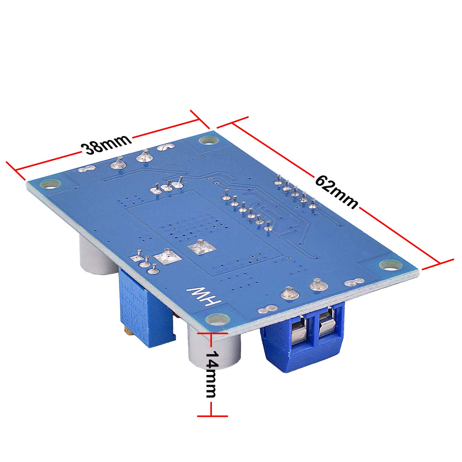
Figure 5: Module dimensions.
10. Warranty and Support
Valefod products are designed for quality and reliability. For any questions, technical assistance, or support regarding your DC-DC Buck Converter, please refer to the seller's contact information or the platform where the product was purchased.
Please retain your proof of purchase for any warranty claims. Specific warranty terms may vary by region and retailer.
Related documentsVA-0189


Ask a question about this manual
Ask about setup, troubleshooting, compatibility, parts, safety, or missing instructions. Manuals+ will review the question and use this page’s manual context to help answer it.