1. Introduction
The Walfront TM919B-1 is a digital programmable timer switch designed for automated control of electrical appliances. It features 24-hour and 7-day programming capabilities, allowing users to set up to 16 ON/OFF programs per day. This device is suitable for controlling lights, fans, and other electrical loads, enhancing energy efficiency and convenience.
This manual provides detailed instructions for the installation, operation, and maintenance of your TM919B-1 timer switch. Please read it thoroughly before use to ensure proper function and safety.
2. Safety Information
- Electrical Hazard: Installation should only be performed by a qualified electrician or knowledgeable individual. Ensure power is disconnected at the circuit breaker before installation or maintenance.
- Voltage Compatibility: This device is designed for AC100-130V power supplies. Do not connect to voltages outside this range.
- Load Capacity: Do not exceed the maximum load capacity of 30A or 5000W. Overloading can cause damage to the device and create a fire hazard.
- Indoor Use Only: This timer switch is intended for indoor use in dry environments. Do not expose to water, moisture, or extreme temperatures.
- Proper Wiring: Follow all wiring diagrams and local electrical codes. Incorrect wiring can lead to malfunction or electrical shock.
3. Product Overview
Familiarize yourself with the components and controls of your Walfront TM919B-1 timer switch.

Image 3.1: Front View of Timer Switch. This image displays the front of the Walfront TM919B-1 timer switch, showing the LCD digital display, the red 'ON' indicator light, and the control buttons: 'P' (Program), 'D+' (Day), 'H+' (Hour), 'M+' (Minute), 'RESET', and 'MANUAL'. The top terminals (1, 2) for power input and bottom terminals (3, 4, 5) for load connection are also visible.

Image 3.2: Angled View with Terminals. This image provides an angled view of the timer switch, highlighting the screw terminals for wiring. Terminals 1 and 2 are for the AC input (L and N), while terminals 3, 4, and 5 are for the load connection (Common, Normally Open, Normally Closed).
3.1. Components and Controls
- LCD Digital Display: Shows current time, day, and programming status (e.g., AUTO, ON, OFF).
- ON Indicator: Red LED light indicating the timer is currently in an ON state.
- P (Program) Button: Used to enter and navigate programming modes.
- D+ (Day) Button: Adjusts the day of the week or selects days for programming.
- H+ (Hour) Button: Adjusts the hour or sets the hour for programming.
- M+ (Minute) Button: Adjusts the minute or sets the minute for programming.
- RESET Button: Clears all settings and returns the timer to factory defaults.
- MANUAL Button: Allows manual override of the programmed state (ON/AUTO/OFF).
- Terminals 1 & 2: Power input (L and N).
- Terminals 3, 4, & 5: Load output (Common, Normally Open, Normally Closed).
4. Specifications
| Feature | Specification |
|---|---|
| Model | TM919B-1 |
| Power Supply | AC 100-130V |
| Frequency | 50/60Hz |
| Load Capacity | 30A / 5000W |
| Time Range | 1 minute - 168 hours |
| Programs | 16 ON/OFF per day (15 combinations per week) |
| Countdown Function | Maximum 24 hours to OFF |
| Clock Display | 12-hour / 24-hour format |
| Internal Battery | CR2450 (for memory backup) |
| Operating Temperature | -10°C to 50°C |
| Mounting | 35mm DIN Rail |
| Material | Plastic |
| Item Weight | 5 ounces |
5. Setup and Installation
5.1. Mounting
The Walfront TM919B-1 timer switch is designed for 35mm DIN rail mounting. Simply clip the device onto a standard DIN rail within your electrical panel or enclosure.

Image 5.1: Timer Switch Dimensions. This image illustrates the physical dimensions of the Walfront TM919B-1 timer switch, showing its height, width, and depth in centimeters, which is useful for planning installation space.
5.2. Wiring
WARNING: Ensure power is OFF at the main circuit breaker before performing any wiring.
The timer switch has five terminals:
- Terminals 1 & 2: Power input for the timer module (AC 100-130V). Connect the Live (L) wire to terminal 1 and the Neutral (N) wire to terminal 2.
- Terminal 3: Common (COM) terminal for the relay output.
- Terminal 4: Normally Open (NO) terminal for the relay output. The circuit between 3 and 4 closes when the timer is ON.
- Terminal 5: Normally Closed (NC) terminal for the relay output. The circuit between 3 and 5 opens when the timer is ON.
Choose the appropriate wiring diagram based on your application:

Image 5.2: Simple Wiring Diagram. This diagram shows a direct connection of the timer switch to a light bulb. The Live (L) and Neutral (N) wires power the timer (terminals 1 and 2). The Live wire is also connected to terminal 3 (Common). Terminal 4 (Normally Open) is connected to one side of the light bulb, and the other side of the bulb is connected to Neutral (N).
For loads exceeding the timer's direct capacity (30A/5000W) or for inductive loads, an external contactor (relay) must be used. The timer switch will then control the coil of the contactor, and the contactor will switch the main load.
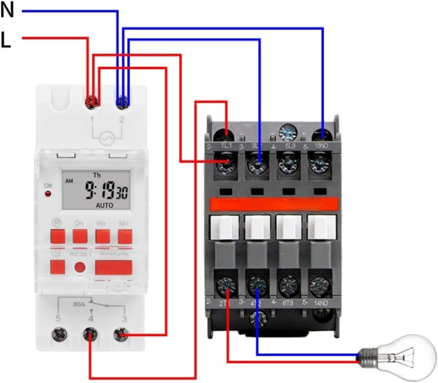
Image 5.3: Wiring Diagram with Contactor. This diagram illustrates how to wire the timer switch with an external contactor to control a higher-power load. The timer's output (terminals 3 and 4) is used to energize the coil of the contactor. The contactor then switches the main power to the load (e.g., a light bulb), ensuring the timer itself is not overloaded.
5.3. Initial Power-Up
After wiring, restore power to the circuit. The LCD display should illuminate. If the display is blank or shows garbled characters, press the RESET button using a pointed object (e.g., a pen tip) to clear the memory and restart the device. The internal CR2450 battery provides memory backup for programmed settings during power outages.
6. Operating Instructions
6.1. Setting Current Time and Day
- Press the P button once. The display will show the current time setting.
- Press D+ to set the current day of the week.
- Press H+ to set the current hour (12-hour or 24-hour format).
- Press M+ to set the current minute.
- To exit the time setting mode, press the P button again or wait for approximately 10 seconds for the display to return to normal operation.
6.2. Programming ON/OFF Events
The timer supports up to 16 ON/OFF programs. Each program consists of an ON time and an OFF time.
- Press the P button repeatedly until '1 ON' appears on the display. This is your first ON program.
- Press D+ to select the day(s) for this program. You can choose a single day, weekdays, weekends, or various combinations (e.g., Mon-Fri, Mon-Sat, etc.).
- Press H+ to set the hour for '1 ON'.
- Press M+ to set the minute for '1 ON'.
- Press P again. '1 OFF' will appear. Set the day(s), hour, and minute for the OFF time of the first program using D+, H+, and M+.
- Repeat steps 1-5 for additional programs (2 ON, 2 OFF, up to 16 ON, 16 OFF). If you do not need all 16 programs, simply stop programming.
- To exit programming mode, press the P button until the display shows the current time, or wait for approximately 10 seconds.
6.3. Manual Override
The MANUAL button allows you to temporarily override the programmed state. Pressing it cycles through the following modes:
- AUTO ON: The timer is currently ON and will follow the next programmed OFF event.
- AUTO OFF: The timer is currently OFF and will follow the next programmed ON event.
- ON: The timer is forced ON, ignoring programs.
- OFF: The timer is forced OFF, ignoring programs.
To return to automatic operation, press MANUAL until 'AUTO ON' or 'AUTO OFF' is displayed.
6.4. Countdown Function
The timer includes a countdown function, allowing you to set a specific duration for the load to be ON or OFF, up to 24 hours.
- From the main time display, press and hold the P button for approximately 3 seconds. The display will show 'd 00:00'.
- Use H+ and M+ to set the desired countdown duration (up to 23 hours and 59 minutes).
- Press P again to start the countdown. The display will show the remaining time.
- Once the countdown finishes, the timer will switch the load to the opposite state (e.g., if it was ON, it will turn OFF).
- To cancel the countdown, press and hold the P button again for 3 seconds.
7. Maintenance
- Cleaning: Wipe the device with a soft, dry cloth. Do not use abrasive cleaners or solvents.
- Battery: The internal CR2450 battery provides memory backup. If the display frequently resets or loses settings during power outages, the battery may need replacement. This typically requires professional service.
- Inspection: Periodically check wiring connections for tightness and signs of wear or damage.
8. Troubleshooting
| Problem | Possible Cause | Solution |
|---|---|---|
| Display is blank or garbled. | No power, incorrect wiring, or internal error. | Check power supply. Verify wiring. Press the RESET button. |
| Programs are not executing. | Timer is in manual ON/OFF mode, incorrect programming, or current time is wrong. | Ensure the display shows 'AUTO ON' or 'AUTO OFF'. Verify program settings. Check and correct the current time. |
| Load does not turn ON/OFF. | Incorrect wiring, faulty load, or overloaded circuit. | Check load wiring (terminals 3, 4, 5). Test the load directly. Ensure load capacity is not exceeded. |
| Settings are lost after power outage. | Internal battery is depleted. | The internal CR2450 battery may need replacement. Contact customer support if this issue persists. |
9. Warranty and Support
Walfront products are manufactured to high-quality standards. For specific warranty information, please refer to the documentation provided at the time of purchase or contact your retailer. If you encounter any issues or require technical assistance, please reach out to Walfront customer support through their official channels or your point of purchase.


