
1. Introduction
The Danfoss KPI 35 Pressure Switch is designed for regulating, monitoring, and alarm systems in various industrial applications. This device is suitable for use with both liquid and gaseous media. It features a single-pole changeover switch (SPDT) for reliable operation.
Key features of the KPI 35 include a high contact load, ultra-short bounce times, vibration resistance (0-1000 Hz, 4g), and a long operating life. Its compact dimensions facilitate easy mounting in control panels.
1.1. Supply Scope
- 1 unit of Danfoss KPI 35 Pressure Switch
- Instruction Manual (this document)
2. Safety Information
Always observe general safety precautions when installing, operating, or maintaining the Danfoss KPI 35 Pressure Switch. Ensure that all electrical connections are made by qualified personnel and comply with local regulations. Disconnect power before performing any installation or maintenance tasks. The device operates with various media; ensure compatibility and proper handling of the specific media in your application.
3. Setup and Installation
The Danfoss KPI 35 is designed for surface mounting and can be easily integrated into control panels due to its small dimensions.
3.1. Mounting
- Select a suitable location for surface mounting, ensuring it is free from excessive vibration and within the specified ambient temperature range.
- Secure the pressure switch using appropriate fasteners.
3.2. Pressure Connection
The pressure connection is G 1/4A. Ensure a tight and leak-free connection to the system where pressure is to be monitored.

Figure 1: Danfoss KPI 35 Pressure Switch showing the G 1/4A pressure connection at the bottom.
3.3. Electrical Wiring
The KPI 35 features a single-pole changeover switch (SPDT) with gold-plated contacts. Refer to the wiring diagram provided with the product for specific connection details. Ensure proper grounding and insulation.
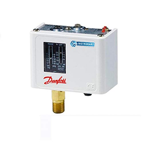
Figure 2: Front view of the Danfoss KPI 35 Pressure Switch, illustrating the display and overall design.
4. Operating Instructions
The Danfoss KPI 35 operates in a manual mode, allowing for precise adjustment of its set points.
4.1. Setting the Pressure Range
The pressure switch has an adjustable measuring range from -0.2 to 8 bar. The differential pressure range is 0.4 to 1.5 bar. Adjust the set point according to your application's requirements using the adjustment mechanism on the unit. Consult the markings on the device for specific adjustment procedures.

Figure 3: Danfoss KPI 35 Pressure Switch, highlighting the visible range and differential pressure settings on the front panel.
4.2. Functionality
- Regulating: The switch can be used to maintain pressure within a desired range by activating or deactivating connected equipment.
- Monitoring: It continuously monitors system pressure, providing feedback on current conditions.
- Alarm Systems: When pressure deviates from the set points, the SPDT contact system can trigger an alarm or safety shutdown.
5. Maintenance
The Danfoss KPI 35 Pressure Switch is designed for a long operating life with minimal maintenance. Regular inspection is recommended to ensure optimal performance and safety.
5.1. Inspection
- Periodically check all connections (pressure and electrical) for tightness and signs of wear or corrosion.
- Ensure the housing is free from damage and that the unit is securely mounted.
- Verify that the operating environment (temperature, vibration) remains within specified limits.
5.2. Cleaning
Clean the exterior of the unit with a soft, dry cloth. Do not use abrasive cleaners or solvents. Ensure no moisture enters the electrical components.
6. Troubleshooting
If the Danfoss KPI 35 Pressure Switch is not functioning as expected, consider the following:
- No Response: Check electrical connections and power supply. Ensure the pressure connection is secure and not blocked.
- Incorrect Switching: Verify that the set pressure range and differential settings are correctly configured for your application. Check for any external factors affecting pressure readings.
- Leakage: Inspect the pressure connection for any signs of leakage. Tighten connections or replace seals if necessary.
- Vibration Issues: While designed to be vibration-proof, extreme vibration outside specified limits may affect performance. Ensure stable mounting.
For persistent issues, contact Danfoss technical support or a qualified service technician.
7. Specifications
| Specification | Value |
|---|---|
| Model Number | KPI-35 |
| Measuring Range | -0.2 to 8 bar |
| Differential Pressure Range | 0.4 to 1.5 bar |
| Permissible Operating Pressure | 18 bar |
| Max. Test Pressure | 18 bar |
| Ambient Temperature Range | –40°C to +65°C |
| Media Temperature Range | –40°C to +100°C |
| Compatible Media | Air, oil, fresh water, liquids, gaseous media |
| Pressure Connection | G 1/4A |
| Contact System | Single-pole changeover switch (SPDT) |
| Contact Material | Gold-Plated |
| Approvals | EN 60 947-4,5 |
| Material | Stainless Steel (connection) |
| Weight | 453.59 g |
| Mounting Type | Surface Mount |
| Operation Mode | Manual |
8. Warranty and Support
For technical assistance, product inquiries, or support, please contact your local Danfoss representative or visit the official Danfoss website. Please note that this item is non-refundable as per the legal disclaimer provided at the time of purchase.


