
QIACHIP cb6b183f-8bf4-4a54-9e07-6dbac4b1be1d
QIACHIP 433MHz Universal Wireless RF Remote Control Switch User Manual
Model: cb6b183f-8bf4-4a54-9e07-6dbac4b1be1d
1. Product Overview
The QIACHIP 433MHz Universal Wireless RF Remote Control Switch is a versatile 1-channel relay kit designed for various low-voltage applications, including LED lighting, Christmas tree lights, and other autonomous control systems. It operates on DC 3.6V-24V and has a maximum load capacity of 2A. This kit offers multiple working modes for flexible control.

Figure 1: QIACHIP 433MHz Universal Wireless RF Remote Control Switch and Receiver.
1.1 Key Features
- Wide Voltage Range: Operates on DC 3.6V to 24V.
- High Sensitivity: Stable and reliable performance with high receiving sensitivity.
- Long Range: Signal can pass through walls, floors, and doors, with a range up to 50m in open space.
- Multiple Work Modes: Supports Momentary, Toggle, Latched, and Delay modes.
- Easy to Use: Simple pairing process for quick setup.
1.2 Package Contents
- 1 x RF Receiver Module
- 1 x Remote Control Transmitter (with 2 CR2032 batteries included)
2. Specifications
| Parameter | Value |
|---|---|
| Working Voltage | DC 3.6V - 24V |
| Maximum Load | 2 Amps |
| Frequency | 433MHz |
| Operating Mode | Automatic |
| Connector Type | Screw |
| Mounting Type | Surface Mount |
| Product Dimensions (Receiver) | 0.89 x 0.43 x 0.31 inches |
| Item Weight | 1.44 ounces |
| Batteries (Remote) | 2 x CR2032 (included) |

Figure 2: Dimensions of the remote control and receiver module.
3. Setup and Wiring
Before proceeding with setup, ensure the power supply is disconnected. Incorrect wiring can damage the device.
3.1 Wiring Diagram
The receiver module has input and output terminals. Connect your power source and the device to be controlled as shown in the diagrams below.

Figure 3: Basic wiring showing Input (DC 3.6V~24V) and Output connections to a light bulb.
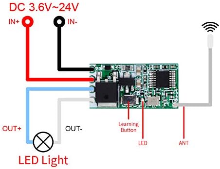
Figure 4: Detailed wiring diagram of the receiver board, indicating IN+, IN-, OUT+, OUT-, Learning Button, LED, and ANT (antenna).

Figure 5: Two examples of wiring for light control, demonstrating different output configurations (positive and negative).
3.2 Pairing the Remote Control
Follow these steps to pair the remote control with the receiver module and set the desired operating mode. The receiver module features a learning button and an LED indicator for this process.

Figure 6: Close-up view of the learning button on the receiver board.
For a visual guide, please refer to the official product video below:
Video 1: QIACHIP Universal Wireless RF Remote Control Switch Setup and Operation Guide. This video demonstrates wiring, clearing existing pairings, and setting up Momentary, Toggle, and Latched modes.
- Clear Existing Pairing:
First, ensure the receiver is powered on. Press the learning button on the receiver 8 times. The LED indicator will flash 8 times, confirming that all existing pairings have been cleared. - Set Momentary Mode:
Press the receiver's learning button 1 time. The receiver's LED will light up, indicating it's in setting state. Now, press one of the buttons (e.g., 'ON' or 'OFF') on the remote control. The LED on the receiver will flash and then turn off, indicating successful pairing for Momentary mode. In this mode, the output is active only while the remote button is pressed. - Set Toggle Mode:
Press the receiver's learning button 2 times. The receiver's LED will light up, indicating it's in setting state. Now, press one of the buttons (e.g., 'ON' or 'OFF') on the remote control. The LED on the receiver will flash and then turn off, indicating successful pairing for Toggle mode. In this mode, pressing the button once turns the output ON, and pressing it again turns the output OFF. - Set Latched Mode:
Press the receiver's learning button 3 times. The receiver's LED will light up, indicating it's in setting state. Now, press the 'ON' button on the remote control. The receiver's LED will flash and remain lit. Then, press the 'OFF' button on the remote control. The receiver's LED will flash and then turn off, indicating successful pairing for Latched mode. In this mode, pressing the 'ON' button turns the output ON, and pressing the 'OFF' button turns the output OFF. - Set Delay Mode (5s/10s/15s):
Press the receiver's learning button 4, 5, or 6 times respectively for 5-second, 10-second, or 15-second delay mode. The receiver's LED will light up. Now, press one of the buttons on the remote control. The LED on the receiver will flash and then turn off, indicating successful pairing. In this mode, pressing the button turns the output ON, and it will automatically turn OFF after the set delay time.
Note: This product is not designed for cloning existing remote signals. It operates as a standalone transmitter/receiver pair.

Figure 7: The remote control is not for cloning other signals.
4. Operating Modes Explained
Understanding the different operating modes is key to utilizing your QIACHIP RF Remote Control Switch effectively.
4.1 Momentary Mode
- Function: The output is active only as long as the remote button is pressed. Releasing the button turns the output off.
- Use Case: Ideal for applications requiring temporary activation, such as a momentary door release or a push-to-talk function.
4.2 Toggle Mode
- Function: Pressing the remote button once turns the output ON. Pressing the same button again turns the output OFF.
- Use Case: Suitable for controlling lights or fans where a single button acts as an on/off switch.
4.3 Latched Mode
- Function: One button (e.g., 'ON') turns the output ON, and another button (e.g., 'OFF') turns the output OFF. The state remains latched until the other button is pressed.
- Use Case: Perfect for applications requiring distinct ON and OFF commands, such as controlling a garage door or a motor's direction.
4.4 Delay Mode
- Function: Pressing the remote button turns the output ON, and it automatically turns OFF after a preset delay (5s, 10s, or 15s).
- Use Case: Useful for timed operations like temporary lighting or activating a device for a specific duration.
5. Maintenance
The QIACHIP RF Remote Control Switch is designed for low maintenance. Follow these guidelines to ensure optimal performance:
- Cleaning: Use a dry, soft cloth to clean the remote and receiver. Do not use liquid cleaners or solvents.
- Battery Replacement: If the remote control's range decreases or the LED indicator on the remote becomes dim, replace the CR2032 batteries. Ensure correct polarity.
- Environmental Conditions: Avoid exposing the receiver module to excessive moisture, extreme temperatures, or direct sunlight.
- Antenna: Do not cut or modify the antenna wire on the receiver module, as this can significantly reduce its range and performance.
6. Troubleshooting
If you encounter issues with your QIACHIP RF Remote Control Switch, try the following troubleshooting steps:
| Problem | Possible Cause | Solution |
|---|---|---|
| Remote not responding | Low or dead remote battery | Replace the CR2032 batteries in the remote. |
| Remote not responding | Receiver not powered | Check power connections to the receiver module. Ensure correct voltage (DC 3.6V-24V). |
| Remote not responding | Pairing lost or incorrect mode set | Clear existing pairings (press learning button 8 times) and re-pair the remote in the desired mode (refer to Section 3.2). |
| Short range or intermittent operation | Obstructions or interference | Ensure the receiver's antenna is not obstructed or near large metal objects. Avoid placing near other RF devices. |
| Short range or intermittent operation | Damaged antenna | Inspect the receiver's antenna for damage. Do not cut or modify it. |
| Device not turning ON/OFF | Incorrect wiring of the controlled device | Verify the output wiring to your device (refer to Section 3.1). Ensure the load does not exceed 2A. |
7. Safety Information
- Always disconnect power before wiring or performing any maintenance on the receiver module.
- Ensure the input voltage (DC 3.6V-24V) and current load (max 2A) are within the specified limits to prevent damage to the device or connected equipment.
- Do not expose the device to water, fire, or extreme temperatures.
- Keep out of reach of children.
- If you are unsure about any wiring or installation steps, consult a qualified electrician.
8. Warranty and Support
QIACHIP products are manufactured to high-quality standards. For warranty information, technical support, or any inquiries, please contact QIACHIP customer service through the retailer's platform or the official QIACHIP website. Please have your product model number and purchase details ready when contacting support.
Related Documents - cb6b183f-8bf4-4a54-9e07-6dbac4b1be1d
 |
QIACHIP KR1201A/KR1201B 12V 1-Channel Receiver: Installation and Operation Guide Comprehensive guide for the QIACHIP KR1201A and KR1201B 12V 1-channel RF relay receiver module. Learn about wiring diagrams, operating modes (Momentary, Toggle, Latching, Delay), and setup procedures for various applications like controlling lights, door locks, and motors. |
 |
Qiachip 1-Channel Receiver Instruction Manual Comprehensive setup and operation guide for the Qiachip 1-Channel RF Receiver. Learn how to wire, reset, and configure Momentary, Toggle, and Latching modes. |
 |
QIACHIP 12V 4-Channel Wireless Receiver Instruction Manual and Technical Specifications Detailed instructions and technical specifications for the QIACHIP 12V 4-Channel Wireless Receiver, covering wiring diagrams, operating modes (Momentary, Toggle, Latching), and setup procedures for wireless remote control applications. |
 |
QIACHIP 12V DC Motor Forward/Reverse Controller Operation Manual This manual provides instructions for operating the QIACHIP 12V DC Motor Forward/Reverse Controller, including wiring diagrams, function descriptions, setting methods for momentary, toggle, and latching modes, and technical specifications. It details how to pair remote controls and reset the device. |
 |
QIACHIP KR1204B 12V 4-Channel Wireless Remote Control Receiver User Manual Comprehensive user manual for the QIACHIP KR1204B 12V 4-Channel Wireless Remote Control Receiver. Includes wiring diagrams, operating modes (Momentary, Toggle, Latching), setup instructions, and technical specifications. |
 |
QA-R-011 Light Control Module Specification Specifications and operating instructions for the QA-R-011 Light Control Module, a wireless RF remote control switch for LED lighting with momentary, toggle, latching, and time delay modes. |
Ask a question about this manual
Ask about setup, troubleshooting, compatibility, parts, safety, or missing instructions. Manuals+ will review the question and use this page’s manual context to help answer it.