
Aexit SR-ML2440
Aexit SR-ML2440 12V/24V 40A MPPT Solar Charge Controller
User Manual
1. Introduction
This manual provides detailed instructions for the installation, operation, and maintenance of the Aexit SR-ML2440 MPPT Solar Charge Controller. This device is designed to efficiently manage power flow from solar panels to batteries, ensuring optimal charging and extending battery life. It features advanced Maximum Power Point Tracking (MPPT) technology for high energy conversion efficiency.

Figure 1: Front view of the Aexit SR-ML2440 MPPT Solar Charge Controller, showing the LCD display and control buttons.
2. Key Features
- Advanced MPPT Technology: Utilizes dual-peak or multi-peak tracking to accurately find the maximum power point, even under partial shading conditions.
- High Efficiency: Achieves up to 99.9% MPPT tracking efficiency and up to 98% circuit energy conversion efficiency, significantly outperforming traditional PWM controllers.
- Versatile Battery Compatibility: Supports various battery types including gel, sealed, open, and lithium batteries with selectable charging programs.
- Intelligent Control: Incorporates multiple tracking algorithms for rapid and precise optimization of the working point on the I-V curve.
- LCD Display: Provides real-time system information and allows for easy parameter configuration.
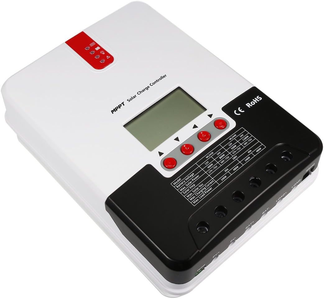
Figure 2: Angled view of the Aexit SR-ML2440 MPPT Solar Charge Controller, highlighting its compact design.
3. Setup and Installation
Before installation, ensure all components are present and undamaged. Disconnect all power sources before wiring to prevent electric shock.
3.1 Wiring Diagram

Figure 3: Wiring diagram showing connections for solar panels, battery, load, and temperature sensor.
3.2 Connection Steps
- Connect the Battery: Connect the battery to the controller's battery terminals (3 and 4 in Figure 3). Ensure correct polarity. The controller will detect the system voltage (12V or 24V) automatically.
- Connect the Solar Panels: Connect the solar panels to the controller's PV terminals (1 and 2 in Figure 3). Ensure correct polarity.
- Connect the Load: Connect the DC load to the controller's load terminals (5 and 6 in Figure 3). Ensure correct polarity.
- Connect the Temperature Sensor: Connect the external temperature sensor (7 in Figure 3) to the designated port on the controller. This is crucial for accurate temperature compensation during charging.
Important: Always connect the battery first, then the solar panels, and finally the load. Disconnect in the reverse order: load, then solar panels, then battery.
4. Operating Instructions
4.1 LCD Display and Buttons

Figure 4: Detailed view of the LCD display interface, showing various icons and parameter values, along with product dimensions.
The LCD display provides real-time operational data and status indicators. Use the control buttons (up, down, enter) to navigate menus and adjust settings.
- System Voltage Indicator: Shows whether the system is operating at 12V or 24V.
- Battery Type Indicator: Displays the currently selected battery type (e.g., GEL, SEALED, OPEN, LI).
- Charging Status: Icons indicate charging stages (e.g., MPPT, BOOST, FLOAT, EQUALIZE).
- Parameter Values: Numeric display for voltage, current, power, and other settings.
4.2 Battery Type Selection
The controller offers various charging programs optimized for different battery chemistries. To select the appropriate battery type:
- Access the battery settings menu via the control buttons.
- Select your battery type from the available options (Gel, Sealed, Open, Lithium).
- Confirm your selection. The controller will then apply the corresponding charging parameters.
Note: Incorrect battery type selection can damage your battery. Refer to your battery manufacturer's specifications.
5. Maintenance
Regular maintenance ensures optimal performance and longevity of your solar charge controller.
- Inspect Connections: Periodically check all wiring connections for tightness and corrosion. Loose connections can cause overheating and power loss.
- Clean the Controller: Keep the controller clean and free from dust and debris. Use a dry cloth for cleaning. Do not use liquids.
- Ventilation: Ensure adequate airflow around the controller to prevent overheating. Do not block ventilation openings.
- Battery Inspection: Regularly inspect your batteries for signs of damage, corrosion, or swelling. Ensure battery terminals are clean.
6. Troubleshooting
If you encounter issues with your solar charge controller, refer to the following common problems and solutions:
| Problem | Possible Cause | Solution |
|---|---|---|
| No display/No power | Battery not connected or low voltage; reversed polarity; blown fuse. | Check battery connections and voltage. Ensure correct polarity. Check for internal or external fuses. |
| Battery not charging | Solar panels not connected; insufficient solar input; reversed PV polarity; faulty PV module. | Verify PV connections and polarity. Check solar panel output. Ensure panels are receiving adequate sunlight. |
| Load not working | Load disconnected; overload protection activated; short circuit in load. | Check load connections. Reduce load if exceeding rated current. Inspect load wiring for short circuits. |
| Overheating | Poor ventilation; excessive ambient temperature; overload. | Ensure proper ventilation. Relocate controller to a cooler environment. Reduce load. |
If the problem persists after attempting these solutions, please contact customer support.
7. Technical Specifications
| Parameter | Value |
|---|---|
| System Voltage | 12V/24V (Auto-detection) |
| Battery Voltage Range | 9V to 35V |
| Max. PV Open Circuit Voltage | 100V (at 25°C), 90V (at -25°C) |
| Max. PV Input Power | 550W (for 12V system), 1100W (for 24V system) |
| Rated Charging Current | 40A |
| Rated Load Current | 20A |
| No-load Loss | 0.7W to 1.2W |
| Operating Temperature | -35°C to +45°C |
| Temperature Compensation Factor | -3mV/°C/2V (default) |
| Installation Hole Diameter | 9.5mm / 0.37in |
| Installation Hole Center Distance | 180mm x 147mm / 7.09in x 5.79in (L*W) |
| Total Size (L*W*H) | 238mm x 173mm x 72.5mm / 9.37in x 6.81in x 2.85in |
| Display Type | LCD |
Note: Battery is not included with the controller.
8. Warranty Information
Specific warranty details for the Aexit SR-ML2440 MPPT Solar Charge Controller are typically provided at the point of purchase or within separate documentation. Please retain your proof of purchase for any warranty claims. For information regarding warranty coverage and terms, please contact the seller or manufacturer directly.
9. Customer Support
For technical assistance, troubleshooting beyond this manual, or inquiries regarding your Aexit SR-ML2440 MPPT Solar Charge Controller, please contact Aexit customer support or your authorized dealer.
Manufacturer: Aexit
Refer to the product packaging or the seller's website for the most current contact information.
Ask a question about this manual
Ask about setup, troubleshooting, compatibility, parts, safety, or missing instructions. Manuals+ will review the question and use this page’s manual context to help answer it.