
HANMATEK DOS1102
HANMATEK DOS1102 Digital Oscilloscope User Manual
Model: DOS1102
1. Introduction
Thank you for choosing the HANMATEK DOS1102 Digital Oscilloscope. This professional, portable 2-channel oscilloscope is designed for electronic engineering, education, research, and development. It features a 110 MHz bandwidth, 500 MS/s real-time sampling rate, and a 7-inch TFT LCD screen, providing precise and reliable waveform analysis.

Figure 1: Various application areas including electronic engineering, education, and research.
2. Safety Information
Please read all safety information carefully before operating the device to prevent personal injury or damage to the oscilloscope or other connected products. Keep this manual for future reference.
- Power Source: Use only the power adapter supplied with the device. Ensure the power supply voltage is within the specified range (100-240V).
- Grounding: Ensure the oscilloscope is properly grounded to prevent electric shock.
- Environment: Operate the device in a dry, well-ventilated area, away from direct sunlight, high temperatures, humidity, and corrosive gases.
- Probes: Use only probes designed for the oscilloscope and ensure they are in good condition. Do not touch the probe tips when connected to a live circuit.
- Maintenance: Do not attempt to service the device yourself. Refer all servicing to qualified service personnel.
- Cleaning: Disconnect power before cleaning. Use a soft, dry cloth. Do not use liquid or aerosol cleaners.
3. Product Overview
3.1. Key Features
- 110 MHz Bandwidth, 500 MS/s Real-time Sampling Rate.
- 2 Channels with 2 ns/div ~ 1000 s/div time base range.
- 7-inch TFT LCD (True Color) display with 800 x 480 pixel resolution.
- Memory depth of not less than 10K sampling points per acquisition.
- Supports U-disk storage function, USB device, and host interface.
- Built-in 6-digit hardware frequency counter (2 Hz ~ 20 MHz).
- Automatic measurement functions (30 types) and waveform detection.
- FFT spectrum analysis function with zoom.
- Automatic cursor function for quick measurements.
- Supports LABVIEW communication and secondary development (SCPI compliant).
3.2. Components and Controls

Figure 2: Front panel of the DOS1102 Oscilloscope with included probes.
The oscilloscope features a clear 7-inch display on the left, showing waveform data and measurement parameters. To the right of the screen are various control knobs and buttons for adjusting settings, navigating menus, and performing measurements.
- Display Screen: 7-inch TFT LCD for waveform visualization and data display.
- Channel Inputs (CH1, CH2): BNC connectors for connecting probes.
- Vertical Controls: Knobs and buttons for adjusting vertical position and scale (mV/div, V/div) for each channel.
- Horizontal Controls: Knobs for adjusting horizontal position and time base (ns/div, s/div).
- Trigger Controls: Settings for stable waveform display.
- Function Buttons: Buttons for Multipurpose, Utility, AutoSet, Run/Stop, Measure, Acquire, Cursor, Math, Menu, Force, and Copy.
- USB Port: Located on the front panel for U-disk storage and host communication.

Figure 3: Detail of the 7-inch TFT (True Color) LCD screen, showing 800x480 pixel resolution.

Figure 4: The USB Device & Host interface for data storage and communication.
4. Setup
4.1. Unpacking and Inspection
Upon receiving your DOS1102 oscilloscope, carefully unpack all components and inspect them for any signs of damage. If any items are missing or damaged, contact your vendor immediately.
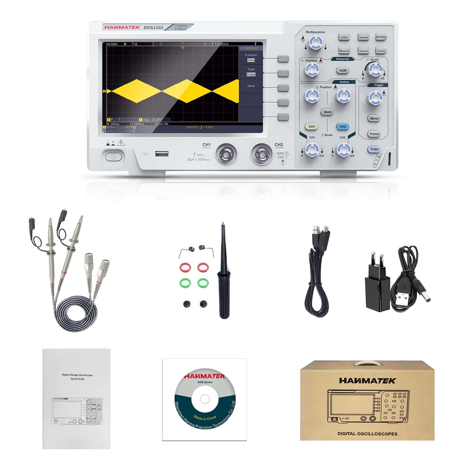
Figure 5: Typical package contents include the oscilloscope, probes, power adapter, USB cable, and user manual.
The standard package typically includes:
- HANMATEK DOS1102 Digital Oscilloscope Unit
- Oscilloscope Probes (2)
- Power Adapter
- USB Cable
- User Manual (this document)
- Software CD (if applicable)
4.2. Connecting Power
- Connect the power adapter to the DC input port on the rear of the oscilloscope.
- Plug the power adapter into a suitable AC power outlet (100-240V).
- Press the power button on the front panel to turn on the oscilloscope.
4.3. Connecting Probes
- Connect the BNC connector of the probe to the CH1 or CH2 input on the front panel.
- Ensure the probe is securely twisted into place.
- Set the attenuation switch on the probe to the desired setting (e.g., 1X or 10X). Remember to match this setting in the oscilloscope's channel menu. The oscilloscope supports 1X, 10X, 100X, and 1000X probe attenuation multipliers.
5. Operating Instructions
5.1. Basic Waveform Display
- Connect a probe to a signal source.
- Press the AutoSet button. The oscilloscope will automatically adjust the vertical, horizontal, and trigger settings to display a stable waveform.
- Use the Vertical Position and Scale knobs to fine-tune the waveform's vertical position and amplitude.
- Use the Horizontal Position and Scale knobs to adjust the waveform's horizontal position and time base.

Figure 6: The oscilloscope in use, demonstrating its 110MHz bandwidth and real-time sampling capabilities.
5.2. Automatic Measurement Functions
The DOS1102 offers 30 automatic measurement functions. To view all measured values:
- Press the Measure button.
- A menu will appear, allowing you to select specific measurements or display all available measurements simultaneously.
- Up to 30 sets of measured values can be displayed at once, simplifying parameter analysis.
5.3. Using the Automatic Cursor Function
This function quickly measures the difference between two points on a waveform.
- Press the Cursor button.
- Select the desired cursor mode (e.g., ΔV for voltage difference, ΔT for time difference, or ΔV & ΔT for both).
- The oscilloscope will automatically position the cursors and display the measured differences.
5.4. FFT Spectrum Analysis
The built-in FFT analysis function converts time-domain signals to the frequency domain.
- Press the Math button.
- Select FFT from the menu.
- Adjust FFT settings such as window type (Hamming, Hanning, Black-Harris) and display units (dB).
5.5. Waveform Zoom Function
To view more details of a waveform:
- Activate the zoom mode. The upper part of the screen will show the main window, and the lower part will show the zoomed-in section.
- Adjust the zoom area using the horizontal position knob.
5.6. Data Storage and Communication
The oscilloscope supports U-disk storage and communication with a host computer.
- U-disk Storage: Insert a USB flash drive into the front USB port. You can save waveforms and screenshots directly to the U-disk. The oscilloscope can store at least 16 groups of waveforms.
- Host Communication: Connect the oscilloscope to a computer using the provided USB cable. The device supports SCPI and LABVIEW communication functions for remote control and data acquisition.

Figure 7: Communication between the oscilloscope and a host computer via USB.
For host software download, please refer to the link provided in the product description or contact HANMATEK support.
6. Maintenance
6.1. General Care
- Keep the oscilloscope clean and free from dust.
- Avoid exposing the device to extreme temperatures, humidity, or direct sunlight.
- Do not drop or subject the device to strong impacts.
6.2. Cleaning
To clean the exterior of the oscilloscope:
- Turn off the oscilloscope and disconnect it from the power source.
- Use a soft, lint-free cloth slightly dampened with water or a mild, non-abrasive cleaner.
- Wipe the surfaces gently. Avoid getting any liquid into the ports or vents.
- Do not use harsh chemicals, abrasive cleaners, or solvents.
6.3. Probe Maintenance
- Inspect probes regularly for any damage to the cable, connector, or tip.
- Store probes properly to prevent kinking or damage to the cables.
- Calibrate probes periodically according to the instructions in the full user manual (if available) or manufacturer guidelines.
7. Troubleshooting
If you encounter issues with your HANMATEK DOS1102 oscilloscope, please refer to the following common problems and solutions before contacting support.
| Problem | Possible Cause | Solution |
|---|---|---|
| No display after power on. | Power cable not connected, power adapter faulty, power button not pressed. | Check power connections. Ensure power button is pressed. Try a different power outlet. |
| No waveform displayed. | Probe not connected, signal source off, incorrect vertical/horizontal settings, trigger issues. | Ensure probe is connected to channel and signal source. Check signal source. Press AutoSet. Adjust vertical/horizontal scales. Check trigger settings. |
| Waveform is unstable or rolling. | Incorrect trigger level or mode. | Adjust the trigger level. Change trigger mode (e.g., to Edge trigger). Ensure trigger source is correct. |
| Cannot save to U-disk. | U-disk not formatted correctly, U-disk full, U-disk faulty. | Ensure U-disk is FAT32 formatted. Check available space. Try a different U-disk. |
| Communication with PC fails. | USB cable faulty, driver not installed, software issues. | Try a different USB cable. Ensure correct drivers are installed on PC. Reinstall host software. |
8. Specifications
The following are the key technical specifications for the HANMATEK DOS1102 Digital Oscilloscope:
| Parameter | Value |
|---|---|
| Model Number | DOS1102 |
| Bandwidth | 110 MHz |
| Real-time Sampling Rate | 500 MS/s |
| Channels | 2 |
| Display | 7-inch TFT LCD (True Color), 800 x 480 pixels |
| Time Base Range | 2 ns/div ~ 1000 s/div |
| Vertical Scale | 20 mV/div ~ 5 V/div |
| Memory Depth | ≥ 10K sampling points |
| Probe Attenuation Multipliers | 1X, 10X, 100X, 1000X |
| Hardware Frequency Counter | 6-digit, 2 Hz ~ 20 MHz |
| Interfaces | USB Device, USB Host |
| Power Supply | DC Power (100-240V AC input via adapter) |
| Product Dimensions (L x W x H) | 30.1 x 15.2 x 7 cm |
| Item Weight | 1.1 kilograms |
| Material | Plastic, Silicone |
| Country of Origin | China |

Figure 8: Physical dimensions of the ultra-portable oscilloscope.
9. Warranty and Support
9.1. Warranty Information
HANMATEK products are manufactured to high quality standards. For specific warranty terms and conditions, please refer to the warranty card included with your product or visit the official HANMATEK website. Typically, a standard manufacturer's warranty covers defects in materials and workmanship under normal use.
9.2. Customer Support
If you require technical assistance, have questions about your product, or need to report an issue, please contact HANMATEK customer support. You can usually find contact information on the official HANMATEK website or through your point of purchase (e.g., "HANMATEK EU-Official store" on Amazon).
When contacting support, please have your product model number (DOS1102) and purchase details ready to facilitate faster service.
Related documentsDOS1102


Ask a question about this manual
Ask about setup, troubleshooting, compatibility, parts, safety, or missing instructions. Manuals+ will review the question and use this page’s manual context to help answer it.