
CCLIFE 1356
CCLIFE Silent Bearing and Bushing Press/Puller Tool Set User Manual
Model: 1356 | Brand: CCLIFE
1. Introduction
This user manual provides comprehensive instructions for the safe and effective operation, maintenance, and troubleshooting of your CCLIFE Silent Bearing and Bushing Press/Puller Tool Set. This 27-piece set is designed for the precise pressing in and out of bearings, seals, and bushings in automotive and industrial applications. It includes 5 robust spindles and 22 pressure pieces to accommodate a wide range of sizes and applications.
2. Safety Information
Always adhere to the following safety guidelines when using the tool set:
- Wear appropriate personal protective equipment (PPE), including safety glasses, gloves, and sturdy footwear.
- Ensure the workpiece is securely fastened before applying pressure.
- Do not exceed the tool's intended capacity. Excessive force can damage the tool or the component.
- Keep hands and fingers clear of moving parts during operation.
- Inspect all components for damage or wear before each use. Do not use damaged tools.
- Keep the work area clean and well-lit.
- Store the tool set properly in its case when not in use to prevent damage and loss.
- Consult a professional if you are unsure about any procedure.
3. Package Contents and Product Overview
The CCLIFE Silent Bearing and Bushing Press/Puller Tool Set (27-piece) includes the following components, neatly organized in a durable blue carrying case:

Figure 3.1: Complete Tool Set in Carrying Case. This image shows the entire 27-piece set, including the spindles and pressure pieces, organized within its robust blue plastic carrying case. The case features secure latches and a handle for easy transport and storage.

Figure 3.2: Set of 5 Spindles. This image displays the five robust threaded spindles, ranging in size from M10 to M18. Each spindle is equipped with nuts and thrust bearings for smooth operation. One spindle is shown with a measurement indicating its length of 35cm.
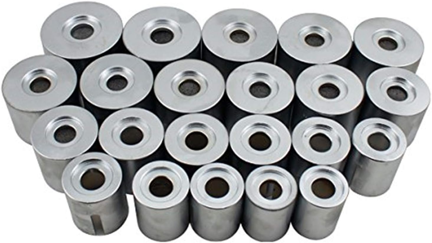
Figure 3.3: Collection of 22 Pressure Pieces. This image shows the 22 cylindrical pressure pieces, also known as sleeves or adapters. These pieces come in various inner diameters (34–80mm) and outer diameters (44–90mm) to fit a wide range of bushings and bearings.

Figure 3.4: Individual Spindle Detail. A closer view of one of the threaded spindles, highlighting the robust construction, the threaded rod, and the integrated thrust bearings on the nuts, which facilitate smooth and powerful pressing or pulling actions.
Component List:
- 5 x Threaded Spindles (M10, M12, M14, M16, M18)
- 22 x Pressure Pieces (Inner Diameter: 34-80mm, Outer Diameter: 44-90mm)
- 1 x Durable Carrying Case
4. Setup
Before beginning any operation, ensure you have selected the correct components for the task.
- Identify the Bushing/Bearing: Determine the exact dimensions of the bushing or bearing to be pressed or pulled.
- Select Appropriate Pressure Pieces: Choose two pressure pieces from the set. One should have an inner diameter slightly larger than the bushing/bearing's outer diameter (for receiving), and the other should have an outer diameter slightly smaller than the bushing/bearing's outer diameter (for pressing).
- Choose the Correct Spindle: Select a spindle (M10-M18) that fits through the center of the bushing/bearing and the chosen pressure pieces. The spindle must be long enough to span the entire assembly.
- Lubricate Threads: Apply a suitable lubricant to the spindle threads and the thrust bearings on the nuts. This reduces friction and extends the life of the tool.
5. Operating Instructions
This section outlines the general procedure for pressing and pulling components. Specific applications may vary.
5.1. Pressing Out (Removal)
- Position the Receiving Cup: Place the larger pressure piece (receiving cup) on one side of the component to be removed, ensuring it is aligned to receive the bushing/bearing.
- Position the Pressing Cup: Place the smaller pressure piece (pressing cup) on the opposite side, directly against the bushing/bearing to be pressed out.
- Insert the Spindle: Thread the selected spindle through the center of the assembly, passing through both pressure pieces and the component.
- Tighten Nuts: Hand-tighten the nuts on both ends of the spindle until the pressure pieces are snug against the component and the receiving cup.
- Apply Force: Using appropriate wrenches on both nuts, slowly and evenly turn them to apply pressure. The bushing/bearing will be pressed into the receiving cup. Ensure the tool remains aligned throughout the process.
- Monitor Progress: Continuously check the alignment and progress. If resistance increases significantly, stop and re-evaluate the setup.
- Remove Component: Once the bushing/bearing is fully pressed out, loosen the nuts and disassemble the tool.

Figure 5.1: Tool in Operation. This image illustrates the tool being used to press out a component. Two wrenches are applied to the nuts on the spindle, demonstrating the manual force application required for the operation. The component is secured in a vise.
5.2. Pressing In (Installation)
- Prepare the Bore: Ensure the bore where the new bushing/bearing will be installed is clean and free of debris. Lightly lubricate the bore if recommended by the component manufacturer.
- Position the New Component: Carefully align the new bushing/bearing with the bore.
- Position Pressure Pieces: Place one pressure piece against the outer edge of the new bushing/bearing (ensuring it only contacts the outer race/shell). Place another pressure piece on the opposite side of the component's housing, acting as a support.
- Insert and Tighten Spindle: Insert the spindle through the assembly and hand-tighten the nuts.
- Apply Force: Slowly and evenly turn the nuts with wrenches to press the new bushing/bearing into the bore. Ensure it enters straight and without binding.
- Verify Installation: Once fully seated, loosen the nuts and remove the tool. Verify that the bushing/bearing is correctly installed and flush.
6. Maintenance
Proper maintenance ensures the longevity and performance of your tool set.
- Cleaning: After each use, wipe down all components with a clean cloth to remove dirt, grease, and debris.
- Lubrication: Regularly apply a light coat of machine oil or grease to the threads of the spindles and the thrust bearings to prevent corrosion and ensure smooth operation.
- Inspection: Periodically inspect all pressure pieces and spindles for signs of wear, bending, cracks, or other damage. Replace any damaged components immediately.
- Storage: Always store the tool set in its original carrying case in a dry, clean environment to protect it from moisture and physical damage.
7. Troubleshooting
| Problem | Possible Cause | Solution |
|---|---|---|
| Excessive force required / Difficulty turning nuts |
|
|
| Tool slipping or damaging component |
|
|
| Spindle bending or breaking |
|
|
8. Specifications
| Attribute | Detail |
|---|---|
| Model Number | 1356 |
| Brand | CCLIFE |
| Number of Pieces | 27 (22 Pressure Pieces, 5 Spindles) |
| Spindle Sizes | M10, M12, M14, M16, M18 |
| Pressure Piece Inner Diameter | 34mm - 80mm |
| Pressure Piece Outer Diameter | 44mm - 90mm |
| Item Weight | 18 Kilograms |
| Product Dimensions | 48 x 35 x 10 cm |
9. Warranty and Support
For warranty information or technical support regarding your CCLIFE Silent Bearing and Bushing Press/Puller Tool Set, please refer to the contact information provided at the point of purchase or visit the official CCLIFE website. Keep your purchase receipt as proof of purchase for any warranty claims.
For additional resources and product information, you may visit the CCLIFE Store on Amazon.
Ask a question about this manual
Ask about setup, troubleshooting, compatibility, parts, safety, or missing instructions. Manuals+ will review the question and use this page’s manual context to help answer it.